Installation instructions, Lamps operated, Mounting the i-160 – IOTA I-160 User Manual
Page 2: Wiring, Installing the charge indicator, Installing the test switch, Page 2
Page 2
7/8" BUSHING
PLASTIC TUBE
CHARGE INDICATOR LAMP
BALLAST CHANNEL
COVER
FLEX CONDUIT
FIXTURE LENS
INSTALLATION INSTRUCTIONS
CAUTION: Before installing, make certain the A.C. power is off and the I-160 unit connector is disconnected.
1. LAmPS OPERATED
Illustration 1 Recessed Troffer Fixture
Illustration 2 Downlight Fixture
I-160
The
I-160 can be used with most 2
′–8′ T8, 2′–4′ T5, or
4-pin compact lamps. Refer to the chart for the type of
lamp(s) operated and the number of lamps to be oper-
ated in emergency mode. Contact Customer Service
with questions about specific lamps.
*The lamp selector leads each have a 3 position short-
ing P-nut connector. Select the proper wire combination
from the chart for the desired lamp(s) used. Cut and
strip one of the selected wires (
3
/
8
″) and plug it into the
P-nut of the second wire.
2. mOUNTINg ThE I-160
Remove the ballast channel cover. mount the
I-160 on
the fixture top in a position that does not interfere with the
existing A.C. ballast or any other hardware. Extend the
flex conduit to a convenient location on top of the fixture
and punch a
7
/
8
″ hole. Feed the wires and flex connector
down through the hole in the fixture and secure in place
with the flex connector nut. An optional T-bar mounting kit is available to mount the
I-160 above the ceiling tile adjacent to the
emergency fixture. To order the optional T-bar mounting kit (part number TBmK-160) contact Customer Service.
When battery packs are remote mounted, consult Customer Service for the maximum allowable distance between the battery pack
and the lamp(s).
CAUTION: Properly secure the I-160 in the ceiling grid to insure compliance with local, state, and federal guidelines
regarding ceiling mounted equipment.
3. WIRINg
Refer to the wiring diagrams on the back page for the appropriate wiring of lamp(s) and ballast. Install in accordance with the
National Electrical Code and local regulations. For additional wiring diagrams consult Customer Service.
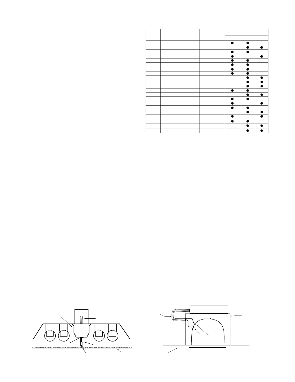
4. INSTALLINg ThE ChARgE INDICATOR
Recessed Troffer Fixture – Select a convenient location with proper clearance in the ballast cover and drill or punch a
7
/
8
″ hole
(
1
/
2
″ knockout). Insert the
7
/
8
″ bushing into the hole. Push the plastic tube through the bushing. Disconnect the leads from the
LED housing and route the leads down the plastic tube. Reconnect the leads to the housing, observing the proper polarity
(Red/Black or Red lead w/connector to positive (+) red tab). Push the entire assembly back into the tube until the lens collar
rests against the plastic tube. The plastic tube should be adjusted so that the
Charge Indicator is within ¼
″ of the fixture lens.
The
Charge Indicator must be visible after installation. Refer to Illustration 1.
Ceiling-Mounted Downlight Fixture – Select a convenient location on the side of the fixture so the
Charge Indicator can be
seen after installation. Allow for proper clearance inside the fixture and drill or punch a
1
/
2
″ hole. Disconnect the leads from
the
LED housing. Push the LED housing into the
1
/
2
″ hole until it is firmly locked in place. Reconnect the leads, observing the
proper polarity (Red/Black or Red lead w/connector to positive (+) red tab). Refer to Illustration 2. For remote mounting the
charge indicator and test switch, the optional RTK accessory kit can be ordered.
Note: For proper operation, use only the accessory components provided with the unit. See Page 1 of the Instruction Manual.
5. INSTALLINg ThE TEST SWITCh
The
Test Switch should be mounted on the ballast channel cover of a recessed troffer, or on the side of a strip fixture, prefer-
ably adjacent to the charge indicator. Drill or punch a
1
/
2
″ mounting hole.
OPTION
LAmP TyPE
EmERgENCy
OPERATION
*LAmP SELECTOR LEADS
Brn/Wht
Brown
Violet
32 Watt 4-ft. T8
One Lamp
59 Watt 8-ft. T8
One Lamp
95 Watt 8-ft. T12
One Lamp
70W Compact
42W Compact
One Lamp
17 Watt 2-ft. T8
Two Lamps
One Lamp
32W Compact
One Lamp
1
2
3
4
5
6
7
28W 4-ft. T5
18W Compact
26W Compact
18W Compact
54W 4-ft. T5
47W 4-ft. T5
39W 3-ft. T5
24W 2-ft. T5
95W 4-ft. T5
8
9
10
11
12
13
14
15
16
Two Lamps
Two Lamps
One Lamp
One Lamp
One Lamp
One Lamp
One Lamp
One Lamp
One Lamp
17 Watt 2-ft. T8
One Lamp
26W Compact
One Lamp
17
18
50W Long Compact
30W Long Compact
One Lamp
One Lamp
25W Long Compact
One Lamp
19
20
21
OBSERVE PROPER POLARITy
FLEX
CEILING
TILE
A.C. BALLAST &
LAMP SOCKET
COMPARTMENT
TEST
SWITCH
CHARGE
LIGHT
I-160