Installation instructions, Lamps operated, Mounting the i-880 – IOTA I-880 User Manual
Page 2: Wiring, Installing the charge indicator, Illustration 1 recessed troffer fixture, Illustration 2 strip fixture
Page 2
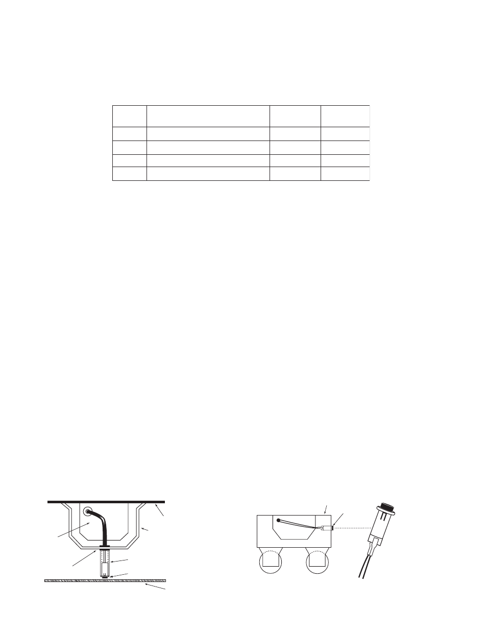
7/8" BUSHING
FIXTURE
BALLAST CHANNEL COVER
PLASTIC TUBE
CHARGE INDICATOR
LIGHT
FIXTURE LENS
INSTALLATION INSTRUCTIONS
CAUTION: Before installing, make certain the A.C. power is off and the I-880 unit connector is disconnected.
1. LAMPS OPERATED
The
I-880 can be used with most
2
′–8′ lamps. Refer to the chart below for the type of lamp(s) operated and the number
of lamps to be operated in emergency mode.
*The 6
″ violet leads provide the lamp selection option. The unit is shipped from the factory with the leads disconnected
and capped. When used with particular lamp types, violet leads should be connected to one another. Refer to chart for
lamp selection options.
2. MOUNTING THE I-880
Remove the ballast channel cover. Mount the
I-880 in the ballast channel at least
1
/
2
″ away from the A.C. ballast(s).
The
I-880 may also be mounted on top of the fixture. The optional top mounting kit (Catalog No. TMK-80) may be
ordered separately from Customer Service.
When battery packs are remote mounted, consult Customer Service for the maximum allowable distance between
the battery pack and lamp.
3. WIRING
Refer to the wiring diagrams on the back page for the appropriate wiring of lamp(s) and ballast. Install in accordance
with the National Electrical Code and local regulations. For additional wiring diagrams consult Customer Service.
4. INSTALLING THE CHARGE INDICATOR
Recessed Troffer Fixture – Select a convenient location with proper clearance in the ballast cover and drill or
punch a
7
/
8
″ hole (
1
/
2
″ knockout). Insert the
7
/
8
″ bushing into the hole. Push the plastic tube through the bushing.
Disconnect the leads from the
LED housing and route the leads down the plastic tube. Reconnect the leads to the
housing, observing the proper polarity (Red/Black or Red lead w/connector to positive (+) red tab). Push the entire
assembly back into the tube until the lens collar rests against the plastic tube. The plastic tube should be adjusted
so that the
Charge Indicator is within ¼
″ of the fixture lens. The Charge Indicator must be visible after installa-
tion. Refer to Illustration 1.
Strip Fixture – Select a convenient location on the side of the fixture so the
Charge Indicator can be seen after
installation. Allow for proper clearance inside the fixture and drill or punch a
1
/
2
″ hole. Disconnect the leads from
the
LED housing. Push the LED housing into the
1
/
2
″ hole until it is firmly locked in place. Reconnect the leads,
observing proper polarity (Red/Black or Red lead w/connector to positive (+) red tab). Refer to Illustration 2.
Illustration 1 Recessed Troffer Fixture
FIXTURE
CHARGE
INDICATOR
LIGHT
(POS LEAD)
RED/BLK OR
RED W/CONNECTOR
WHITE/RED
LEAD
+ RED
Illustration 2 Strip Fixture
I-880
OBSERVE PROPER POLARITY
I-880
2 -4 T-8/T-12 Single & Bipin Pin
1
LAMP TYPE
OPTION
2
5 -8 T-8/T-12 Single & Bipin Pin
EMERGENCY
OPERATION
One Lamp
One Lamp
*VIOLET
LEADS
Connected
Disconnected
3
2 -4 T-8/T-12 Single & Bipin Pin
Two Lamp
Disconnected
4
2 -4 28W, 54W T5
One Lamp
Connected