Hanna Instruments HI 700 Series User Manual
Page 8
15
14
Code
Valid Values
Default
PW
14 Relay 1 deviation (D1)
0.5 to 10% f.s.
1% f.s.
no
15 Relay 1 reset time
0.1 to 999.9 minutes
999.9
no
16 Relay 1 rate time
0.0 to 999.9 minutes
0.0
no
21 Relay 2 mode (M2)
same as relay 1
0
no
22 Relay 2 setpoint (S2)
0.5 to 99.5% full scale
75% f.s.
no
23 Relay 2 hysteresis (H2)
0 to 5% f.s.
1% f.s.
no
24 Relay 2 deviation (D2)
0.5 to 10% f.s.
1% f.s.
no
25 Relay 2 reset time
0.1 to 999.9 minutes
999.9
no
26 Relay 2 rate time
0.0 to 999.9 minutes
0.0
no
30 Relay 3 high alarm (HA) 0.5 to 99.5% full scale
95% f.s.
no
HA-Hys LA
+
Hys,Hys
=
1.5%f.s.,HA S1 or HA S2
31 Relay 3 low alarm (LA)
0.5 to 99.5% full scale
5% f.s.
no
LA
+
Hys HA-Hys,Hys
=
1.5%f.s.,LA S1 or LA S2
32 Proportional control
1 to 30 min
5
no
mode period
33 Maximum relay ON time 10 to 9999 min
60
no
(after which an alarm mode is entered)
34 Alarm mask time
00:00 to 30:00
00:00
no
40 Analog output selection
0: 0-1mA
2
no
1: 0-20 mA
2: 4-20 mA
3: 0-5 VDC
4: 1-5 VDC
5: 0-10 VDC
41 Analog output
0 to 100% full scale
0
no
lower limit (O_VARMIN) (O_VARMIN O_VARMAX - 5% f.s.)
42 Analog output
0 to 100% full scale
100% f.s.
no
upper limit (O_VARMAX) (O_VARMIN O_VARMAX - 5% f.s.)
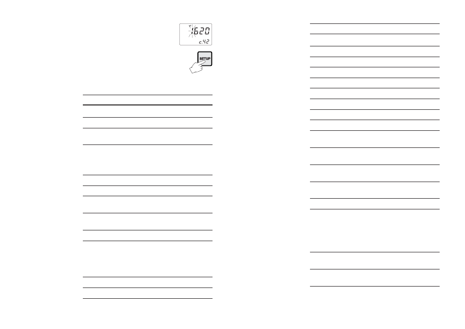
• After confirmation, the selected parameter
is displayed. The user can scroll through
the parameters by pressing CFM.
In order to directly set another param-
eter, press SETUP again and enter the
code or scroll to it by pressing CFM.
The following table lists the setup codes along with the descrip-
tion of the specific setup items, their valid values and whether
password is required to view that item (“PW” column):
Code
Valid Values
Default
PW
00 Factory ID
0 to 9999
0000
no
01 Process ID
0 to 99
00
no
02 Control enable/disable
0: C.M. disabled
0
no
1: C.M. enabled
03 Range
1: 0.0-199.9 μS (or 100.0 ppm) 4
no
(depends on model) 2: 0-1999 μS (or 1000 ppm)
3: 0.00-19.99 mS (or 10.00 ppt)
4: 0.0-199.9 mS (or 100.0 ppt)
04 Reference Temperature
20°C or 25°C
25°C
no
05 Temperature Coefficient
0.00 to 10.00 %/°C
2.00
no
06 Input Selection
0: conductivity probe
0
no
1: 4-20 mA input signal
07 Temperature
ATC: Automatic
ATC
no
compensation
User: Manual
08 TDS Factor (HI710 only) 0.00 to 1.00
0.50
no
11 Relay 1 mode
0: disabled
0
no
(M1)
1: ON-OFF high setpoint
2: ON-OFF low setpoint
3: PID, high setpoint
4: PID, low setpoint
12 Relay 1 setpoint (S1)
0.5 to 99.5% full scale
25% f.s.
no
13 Relay 1 hysteresis (H1)
0 to 5% f.s.
1% f.s.
no