Control mode – Hanna Instruments HI 700 Series User Manual
Page 10
19
18
An upper boundary is imposed for dosage time when relays
are energized continuously, i.e. when relay works in ON/
OFF mode or also in PID mode but in the latter case only if
the relay is always ON. This parameter can be set through
setup procedure. When the maximum boundary is reached,
an alarm is generated; device stays in alarm condition until
relay is de-energized.
ON/OFF CONTROL MODE
Either for mode 1 or 2 (high or low conductivity dosage) the
user has to define the following values through setup:
• relay setpoint (
μS/mS/ppm value);
• relay hysteresis (
μS/mS/ppm value).
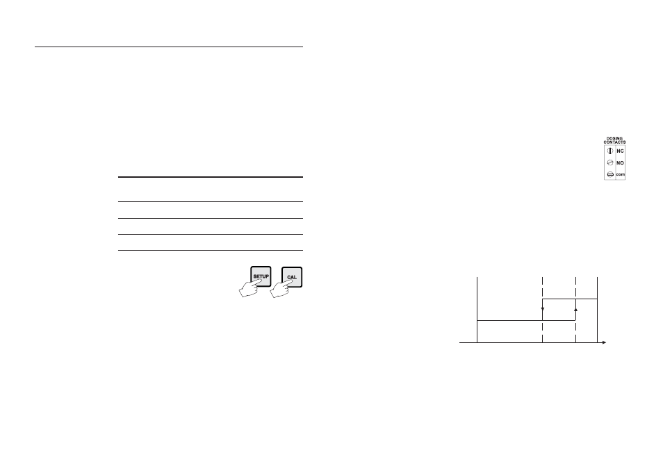
Connect your device to the COM and NO
(Normally Open) or NC (Normally Closed)
terminals.
The ON relay state occurs when relay is energized (NO and
COM connected, NC and COM disconnected).
The OFF relay state occurs when relay is de-energized (NO
and COM disconnected, NC and COM connected).
The following graphs show relay states along with EC mea-
sured value (similar graph can be derived for TDS control).
As shown below, a high setpoint relay is activated when the
measured EC exceeds the setpoint and is deactivated when it
is below the setpoint value minus hysteresis.
Such a behavior is suitable to control a high conductivity
dosing pump.
A low setpoint relay as can be seen from the following graphs
is energized when the EC value is below the setpoint and is
de-energized when the EC value is above the sum of setpoint
and the hysteresis. The low setpoint relay may be used to
ON
OFF
Setpoint
EC
Setpoint –
Hysteresis
CONTROL MODE
The control mode is the normal operational mode for these
meters. During control mode the meter fulfills the following
main tasks:
• converts information from EC/TDS and temperature inputs
to digital values;
• controls relays and generates the analog outputs as deter-
mined by the setup configuration, displays alarm condition;
In HI 710 models it is possible to switch between EC and
TDS reading pressing “LCD”. The TDS value is obtained mul-
tiplying the EC measurement by the TDS factor set through
setup. The HI 700 models display EC only.
The status of the meter is shown by the LED’s on the right.
STATUS
LEDs
Control
Alarm
Alarm LED (green) Relay LED (yellow)
Red LED
OFF
----
ON
OFF
ON
ON
OFF
ON
ON or OFF
OFF
ON
ON
OFF
ON or OFF
Blinking
Meter exits control mode by pressing
SETUP or CAL and confirming the
password. Note that this command
generates a temporary exit. To deacti-
vate the control mode definitively, set
CONTROL ENABLE to “0” (item #
02).
RELAY MODES
Once enabled, the relays 1 and 2 can be used in four differ-
ent modes:
1) ON/OFF, high setpoint (low conductivity dosage);
2) ON/OFF, low setpoint (high conductivity dosage);
3) PID, low setpoint (low conductivity dosage);
4) PID, high setpoint (high conductivity dosage).