Hanna Instruments HI 700 Series User Manual
Page 6
11
10
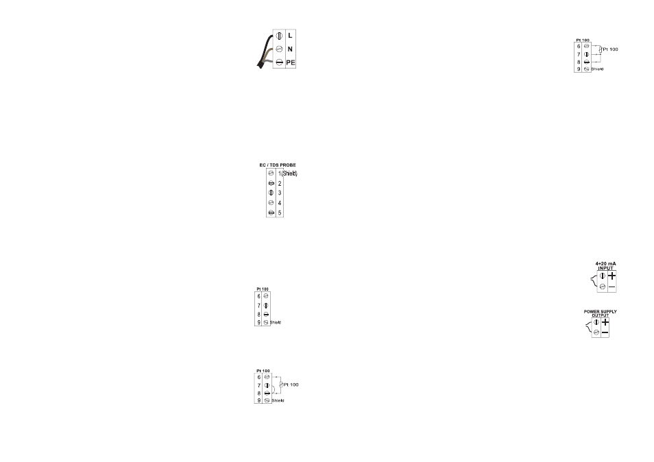
If the Pt 100 has more than 2 wires, con-
nect the two wires of one end to pins 7
and 8 (pin 7 is an auxiliary input to com-
pensate for the cable resistance) and one
wire from the other end to pin 6. Leave
the fourth wire unconnected, if present.
Note
If the meter does not detect the temperature probe, it will
switch automatically to manual temperature compensation
with the temperature adjustable through the up and down
arrow keys. The “°C” symbol will blink on the LCD.
Note
All external cables to be connected to the rear panel should
be ended with cable lugs.
• Analog output: Connect an external recorder with a 2-wire
cable to these terminals (#2 on page 7) paying attention
to the correct polarity. A wide variety of output signals,
either in V or in mA, is available to fit most standards.
• Contact 1 and 2: Connect the dosing devices to these
terminals (#5 and #8 on page 7) in order to activate and
deactivate them according to the selected control param-
eters.
• mA Input: to switch to mA input signal from a
conductivity transmitter (e.g. HI8936, HI98143
or HI98144 series) see setup procedure (code
6). Connect the two signal wires from the trans-
mitter to terminals #12 on page 7, paying at-
tention to the correct polarity.
An unregulated 10 to 30 VDC - 50 mA max.
power supply output (#11 on page 7) is pro-
vided to power the transmitter, if needed.
Once the installation is completed, select the appropriate
working range, the reference temperature (20 or 25°C) and
perform conductivity or TDS calibration as described in this
instruction manual. Set the control parameters according to
the process.
• Power Supply: Connect a 3-wire power cable
to the terminal strip, while paying attention
to the correct live (L), earth (PE) and neu-
tral (N) terminal connections.
Power: 115 Vac -100 mA / 230 Vac - 50 mA.
Live Contact: fused inside 400 mA.
PE leakage current 1 mA; this contact must be con-
nected to ground.
• Conductivity input: the default input is from conductivity
probe. Connect the EC probe to the terminals #10 on
page 7. Connect the cable shield to pin 1, and the other
four wires according to the following table:
Color
Pin #
GREEN
2
WHITE
3
RED
4
BLUE
5
• Pt 100 Terminals: these contacts (#9 on page 7) connect
the Pt 100 temperature sensor for automatic temperature
compensation of measurement. The HI7639 EC/TDS probe
has a built-in 3-wire Pt 100 sensor to be connected ac-
cording to the following table:
Color
Pin #
GRAY
6
BROWN
7
YELLOW
8.
If using a different Pt 100, separated from the conductivity
probe, connect the cable shield to pin 9, and the other
wires as explained below.
In the case of a 2-wire sensor connect
the Pt 100 to pins 6 and 8, and short
pins 7 and 8 with a jumper wire.