Hanna Instruments HI 700 Series User Manual
Page 13
25
24
This is an important feature since with most meters the alarm
terminals close only when an abnormal situation arises, how-
ever, due to line interruption, no alarm
is sounded, causing extensive damage.
On the other hand, software is em-
ployed to set off the alarm in abnormal
circumstances, for example, if the dos-
ing terminals are closed for too long a
period. In both cases, the red LED’s will
also provide a visual warning signal.
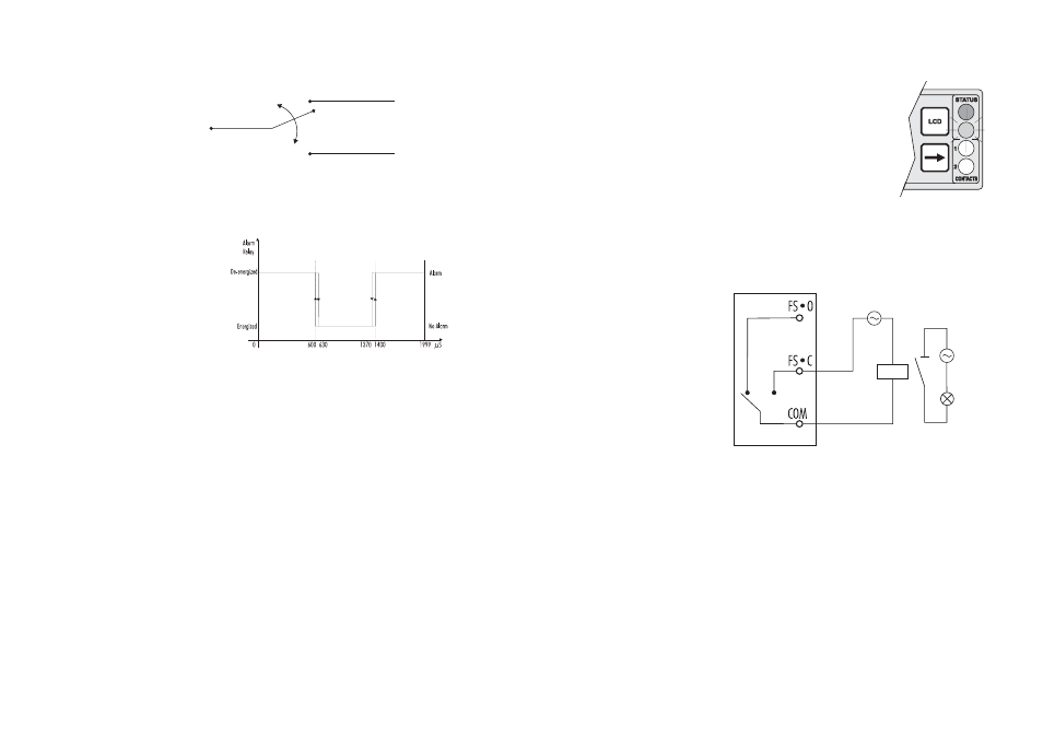
The Fail Safe mode is accomplished by connecting the exter-
nal alarm circuit between the FS•C (Normally Open) and
the COM terminals. This way, an alarm will warn the user
when EC exceeds the alarm thresholds, during power down
and in the case of a broken wire between the process meter
and the external alarm circuit.
Note
In order to have the Fail Safe feature activated, an external
power supply has to be connected to the alarm device.
CONTROL THROUGH ANALOG OUTPUT
Models HI 700221 and HI 710221 have a proportional
analog signal (selectable among 0-1mA, 0-20mA, 4-20mA,
0-5VDC, 1-5VDC and 0-10VDC) at the analog output ter-
minals. With this output, the actual output level amplitude is
varied, rather than the proportion of ON and OFF times
(duty cycle control). A device with analog input (e.g. a pump
with a 4-20 mA input) can be connected to these terminals.
FS•O = NC (Normally Closed)
De-energized Relay
COM
FS•C = NO (Normally Open)
Energized Relay
ALARM RELAY
The alarm relay functions in the following manner:
During alarm condition, the relay is de-energized. When not
in alarm condition, the relay is energized.
Example:
High alarm set at 1400
μ S
Low alarm set at 600
μS
An hysteresis will eliminate the possibility of continuous se-
quences ‘energizing/de-energizing’ of the alarm relay when
the measured value is close to the alarm setpoint. The alarm
hysteresis amplitude is 1.5% of full scale.
Moreover the alarm signal is generated only after a user se-
lectable time period (alarm mask) has elapsed since the
controlled value has overtaken one alarm threshold. This
additional feature will avoid fake or temporary alarm condi-
tions.
Note
If the power supply is interrupted, the relay is de-energized as
if in alarm condition to alert the operator.
In addition to the user-selectable alarm relays, all EC/TDS
controllers are equipped with the Fail Safe alarm feature.
The Fail Safe feature protects the process against critical
errors arising from power interruptions, surges and human
errors. This sophisticated yet easy-to-use system resolves these
predicaments on two fronts: hardware and software. To elimi-
nate problems of blackout and line failure, the alarm function
operates in a “Normally Closed” state and hence alarm is
triggered if the wires are tripped, or when the power is down.