Hanna Instruments HI 700 Series User Manual
Page 16
31
30
CONNECTIONS
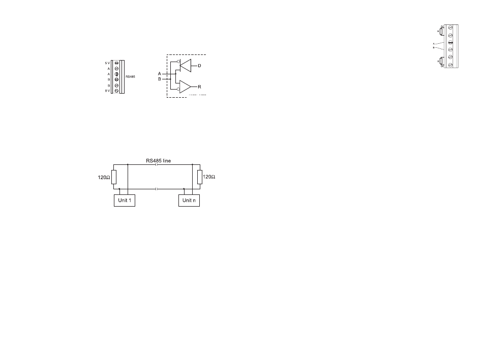
The connections for the 6-pin RS485 terminal provided (#1
on page 7) are as follows:
There is an internal short between the two A pins and be-
tween the two B pins.
The instrument has no internal line termination. To terminate
the line, an external resistor equal to the characteristic line
impedance (typically 120
Ω) must be added at both ends of
the line.
Up to 32 units can be connected to the same RS485 line,
with a total line length of up to 1.2 Km using 24AWG cable.
To minimize electromagnetic interferences, use shielded or
twisted pair cable to connect the units.
Each unit is identified by its process ID number (setup item
“01”).
The controller acts as a “slave” device: it only answers to
commands received from a “master” device (e.g. an indus-
trial PC) connected to the line.
As additional feature, the controller is also
provided with two pins (5V and 0V) in
order to apply the Fail Safe Open Line
protection method. To avoid erroneous
readings in Open-Line conditions, pull-
up and pull-down resistors should be
connected as shown.
The Fail-Safe resistors are connected only to one unit in the
line, and their value depends on the application and char-
acteristic impedance of the connection cable.
The RS485 port is optoisolated from measuring circuit and
power line. The analog output and RS485 port have the same
ground.
RS485 PROTOCOL
The commands sent to the controller must have the following
format:
• 2-digit process ID number
• 3-character command name
• Parameters (variable length, may be null)
• End of command (always the CR character, Hex 0D)
A maximum time interval of 20 ms is allowed between two
consecutive characters of a command.
It is possible to send commands to change the controller
settings or to simply ask information on the controller status.
Following is the complete list of commands available: