Hanna Instruments HI 943500A User Manual
Page 9
17
16
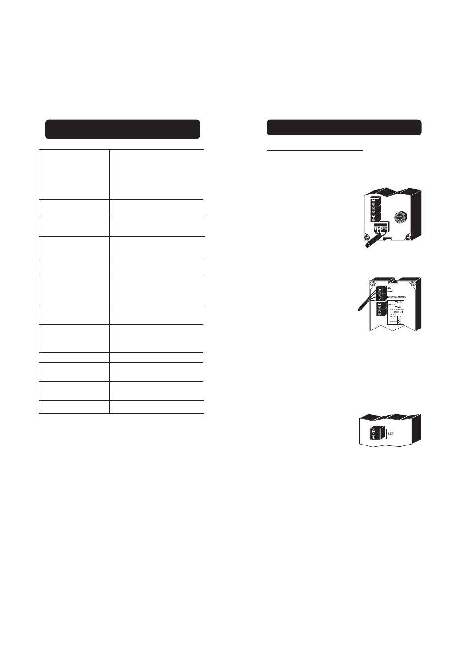
CONNECTIONS
REAR CONNECTIONS FOR HI 8931
•
Power Connection Terminals
4-screw-terminal-strip for connection
to a 3-wire power cable according to
the indicated voltage (115 or 230V).
•
IN/OUT Transmitter
2 wires of the 4-core signal cable
from the conductivity transmitter
(HI8936) have to be connected to
the mA input terminals and the
other 2 wires to the "+20 V" and
"COM" while paying careful atten-
tion to the polarity.
+20 V supply is the regulated DC supply required for the
operation of the external conductivity transmitter HI 8936.
•
Set Contacts
Dosing pumps or other control equip-
ment may be connected to the "SET"
(Max. 2A, 240 V) terminals. These
contacts act only as a "dry" switch
allowing electrical continuity, not as
a power supply.
SPECIFICATIONS HI 8936
0.0 to 199.9 mS/cm
0.00 to 19.99 mS/cm
0 to 1999 μS/cm
0.0 to 199.9 μS/cm
±2% of Full Scale
excluding probe error
±2% of Full Scale
±0.4 mA
HI 7635 for in-line applications or
HI 7638 for tank (not included)
Manual, 2 point, through
offset and slope trimmers
Fixed or automatic
from 0 to 50°C (32 to 122°F)
with ß=2%
4 to 20 mA not-isolated
max. 500 Ohm
12 to 30 Vdc
17 to 36 Vdc
IP 65
0 to 50°C (32 to 122°F);
RH max 95%
165 x 110 x 90 mm
(6.5 x 4.3 x 3.5")
1 kg (2.2 lb.)
Range
HI 8936 A/AL
HI 8936 B/BL
HI 8936 C/CL
HI 8936 D/DL
Accuracy
(@20°C/68°F)
Typical EMC
Deviation
Conductivity Probe
Calibration
Temperature
Compensation
Output
Power Supply
HI 8936 A/B/C/D
HI 8936 AL/BL/CL/DL
Protection
Environment
Dimensions
Weight