Hanna Instruments HI 943500A User Manual
Page 4
7
6
Unplug the instrument from power supply before
replacing the fuse.
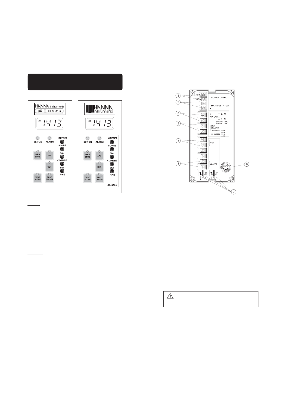
REAR PANEL OF HI 8931 SERIES
1.
POWER OUTPUT terminals (+20 V and COM) for connec-
tion to a conductivity transmitter (HI 8936)
2.
mA INPUT from a conductivity transmitter
3.
mA OUTPUT terminals for connection to a recorder
4.
SET SELECT terminals for reverse control operation
5.
SET terminals for connection to a dosing pump
6.
ALARM terminals for connection to an external alarm device
7.
Power supply terminals
8.
Fuse holder
FUNCTIONAL DESCRIPTION
HI 8931 & HI 943500
KEYPAD
MEASURE
To read measurements and enable diagnostic tests
ΔAL
To display set tolerance of the alarm
SET
To set working point
TEST SLOPE
Diagnostic function
TEST OFFSET
Diagnostic function
When a key is pressed, the corresponding LED lights up to indicate that
the function is active.
TRIMMERS
OFFSET
For offset calibration
SLOPE
For slope calibration
ΔAL
To set the alarm tolerance
COARSE
To coarsely adjust the set point
SET FINE
To finely adjust the set point
LEDS
SET ON
To indicate that the dosage is active
ALARM
To indicate an alarm condition