Hanna Instruments HI 943500A User Manual
Page 13
25
24
INITIAL PREPARATION & INSTALLATION
Material needed:
• a 3-wire power cable (to connec the HI 8931 or HI 943500 to
the mains)
• a PVC insulated 4-core cable (to connect the HI 8931 to HI8936)
• rubber seals and a pipe sealant (for installation of HI 7635)
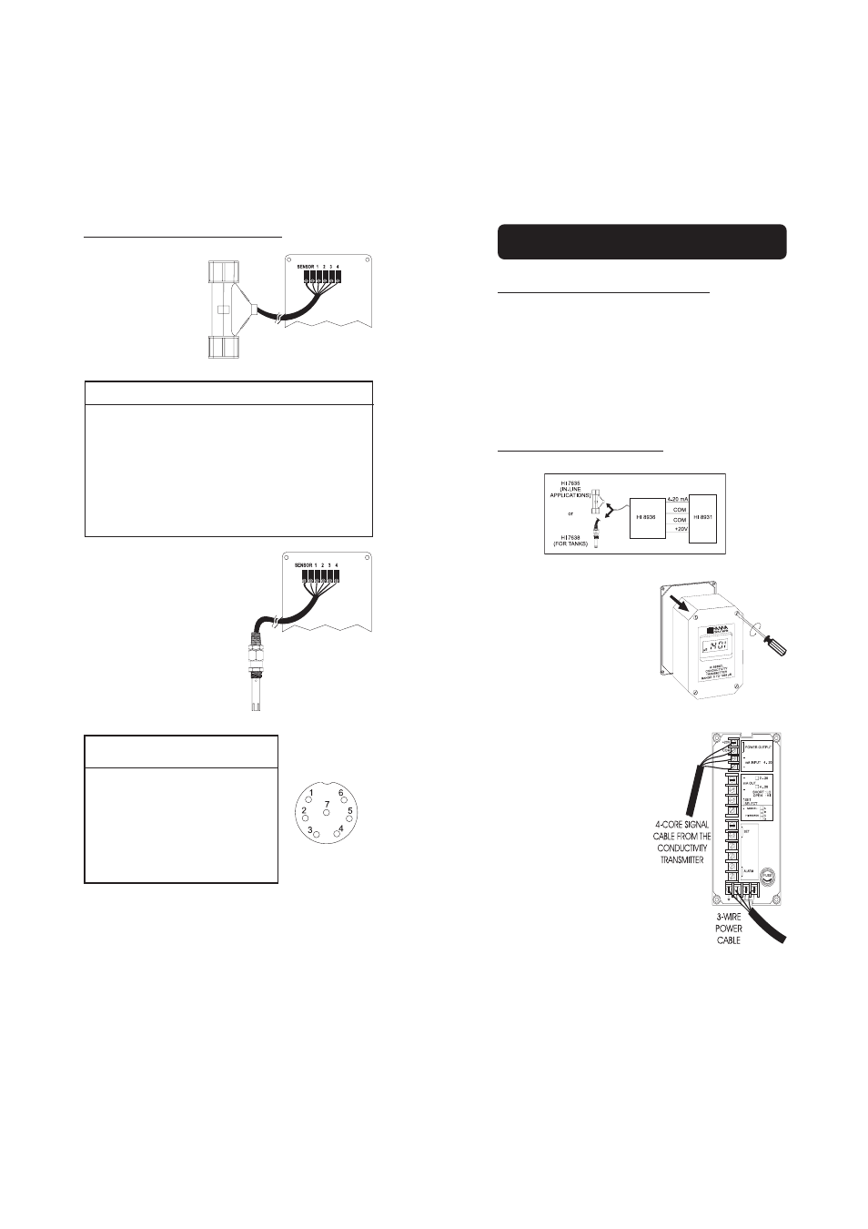
FOR HI 8931 AND HI 8936 ONLY
• Remove the 4 screws and the
top of the HI 8936 conductivity
transmitter.
• Connect the 2 wires connected to
the "4-20 mA" and "COM" ter-
minals of the 4-core signal cable
from the HI 8936 to the termi-
nals marked "mA input" paying
careful attention to polarity.
Connect the other 2 wires to the
"+20 V" and "COM" terminals,
while paying attention to the
polarity.
• Connect the 3-wire power cable
to the 4-screw terminal strip ac-
cording to the voltage level as
indicated, and pay particular
attention to the correct live, earth
and neutral terminal connections.
OPERATIONAL GUIDE
CONDUCTIVITY PROBE CONNECTIONS
The connections for HI 7635
are color coded for easy in-
stallation and are as fol-
lows:
HI 7635 cable
HI 8936 transmitter
Black or Grey
NTC
Red or Pink
SENSOR
Brown or Orange
probe pin 1
Blue
probe pin 2
White
probe pin 3
Green or Yellow
probe pin 4
The connections for HI 7638 are
as follows:
HI 7638
HI8936 transmitter
#1
probe pin 1
#2
probe pin 2
#3
probe pin 3
#4
probe pin 4
#5
NTC
#6
SENSOR
Note: NTC & SENSOR are equivalent, and are both labeled
"SENSOR" on the HI 8936 conductivity transmitter.
connector
inside view