Side view of the panel-mounted unit – Hanna Instruments HI 943500A User Manual
Page 5
9
8
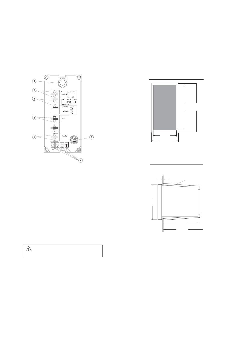
MECHANICAL DIMENSIONS
OF HI 8931 AND HI 943500
Front view of the panel-mounted unit
These dimensions show the cutout size for the installation.
Side view of the panel-mounted unit
Adjustable location brackets (supplied with the meter) allow the indicator
to slide into the cutout and will hold the unit securely in place. 190 mm
(7.50") is the minimum amount of room required to install the indicator
with the cables connected.
190mm MIN
7.50"
135mm
5.31"
0.25/4mm
0.01/0.160"
144mm
5.67"
ADJUSTABLE
LOCATION
BRACKET
141mm
5.55"
144mm
5.67"
69mm
2.71"
72mm
2.83"
REAR PANEL OF HI 943500 SERIES
1.
DIN connector for conductivity probe
2.
mA OUTPUT terminals for connection to a recorder
3.
SET SELECT terminals for reverse control operation
4.
SET terminals for connection to a dosing pump
5.
ALARM terminals for connection to an external alarm device
6.
Power supply terminals
7.
Fuse holder
Unplug the instrument from power supply before
replacing the fuse.