2 water system – Glow-worm EnergySaver 80 User Manual
Page 9
9
221837B
0246M
2 Water System
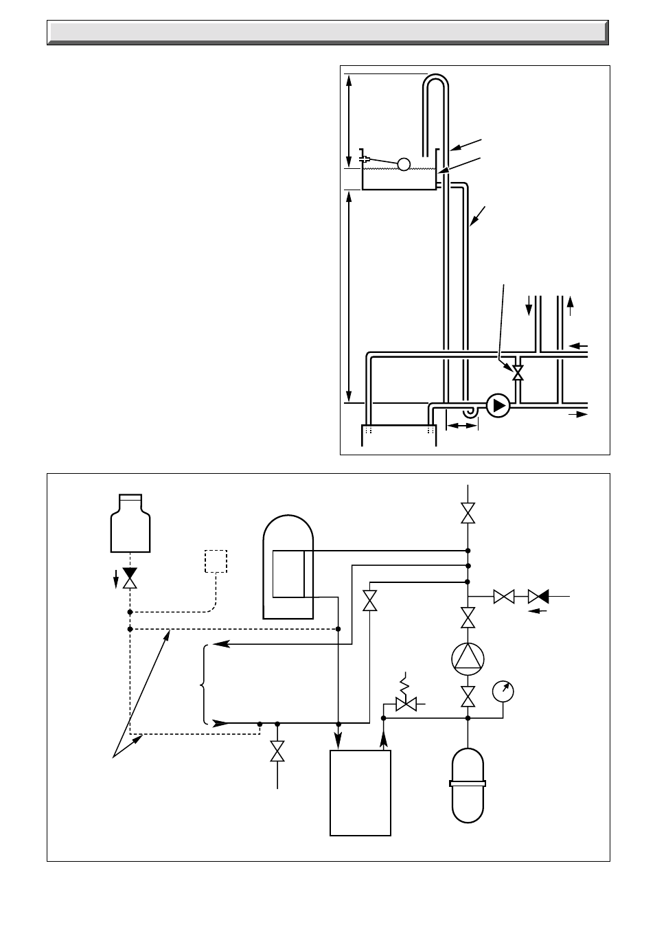
Diagram 2.3
Diagram 2.4
3 LITRES (0.66 gals)
MAKE-UP BOTTLE
(if required)
NON-RETURN
VALVE
AUTO
AIR
VENT
FLOW
DRAIN
COCK
BOILER
SAFETY
VALVE
(Make-up
alternatives)
EXPANSION
VESSEL
PRESSURE
GAUGE
CIRCULATING
PUMP
FILLING POINT
AIR
RELEASE
POINT
HEATING
CIRCUIT
22mm (min)
BY-PASS WITH
LOCKSHIELD
VALVE
RETURN
Open (vented) ststem.
Recommended
rellationship between
pump,cold feed and vent.
22mm (MIN.) VENT
FEED AND
EXPANSION
CISTERN
15mm (MINIMUM)
COLD FEED
22mm (MINIMUM) BY-
PASS WITH
LOCKSHIELD VALVE
1150mm
MIN.
BOILER
150mm
MAX
FLOW
PUMP
RET.
CYLINDER
FLOW
RET.
HEATING
450mm
MIN.
HEIGHT
2.8 Domestic Hot Water System - Unvented
Where a storage system will not have a vent to atmosphere the
installation must comply with the Building Regulations and local
Water Company bylaws, see also the current issue of BS5546
and BS6700.
If fitting to an existing system the local authority should be
informed.
2.9 Sealed Water Systems
The installation must comply with the appropriate requirements
of the current issue of BS4814, BS5449, BS6759, BS6798 and
BS7074 Part 1 and 2.
See diagram 2.4 for a suggested layout.
2.10 Safety Valve
A safety valve must be fitted to a sealed system.
It shall be preset, nonadjustable with a lift pressure of 3bar,
incorporating seating of a resilient material, a test device and a
connection for drain.
The drain from the safety valve must be routed clear of any
electrical fittings and positioned so that any discharge can be
seen.
5814