14 replacement of parts – Glow-worm 18-30sxi Range User Manual
Page 47
47
0020008155A
Diagram 14.22
REAR
PANEL
TORX
SCREWS (3)
CONTROL
BOX
RETAINING
STRAP
RETAINING
SLOTS
Diagram 14.23
USER INTERFACE
SECURING SCREWS
14 Replacement of Parts
Diagram 14.24
230V CONTROLS
INTERFACE BOARD
USER
INTERFACE
11419
PCB RETAINING
CLIPS
12411
FUSE
MAIN PCB
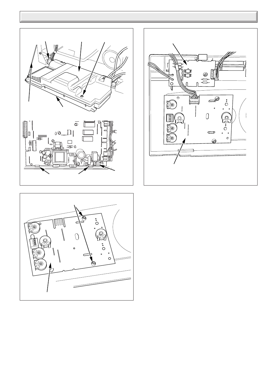
14.35 Fuse - Main PCB - Control Box
For access, refer to section 14.33.
The fuse (rated 630mAT) is located at bottom right hand side of
the PCB, see diagrams 13.2 or 14.22.
14.36 230V Controls Interface
For access, refer to section 14.29.
Disconnect the electrical connection from the 230V controls
board and the electrical connection from the Main PCB, see
diagram 14.24.
Remove the 230V controls interface retaining screw.
Remove the 230V controls interface board.
See also other documents in the category Glow-worm Water boiler:
- 12-38hxi Range (44 pages)
- 23c (44 pages)
- 24-38CXI Range (52 pages)
- 30ci Plus (56 pages)
- BBU 45/4 (32 pages)
- BBU 54/4 (32 pages)
- Betacom C (68 pages)
- Betacom2 (8 pages)
- Betacom2 (20 pages)
- Betacom2 (56 pages)
- Black Beauty 4 (20 pages)
- Chatsworth 4 (24 pages)
- Clearly Heat Recovery (20 pages)
- Clearly Heat Recovery (32 pages)
- Clearly Heat Pumps Envirosorb3 (28 pages)
- Clearly Heat Pumps Envirosorb2 (44 pages)
- Clearly Heat Pumps 7kW (44 pages)
- Clearly Heat Pumps 5kW (28 pages)
- Clearly Heat Pump 5kW (16 pages)
- Clearly Heat Pump 5 kW (32 pages)
- Clearly Heat Pump - Buffer Vessel (10 pages)
- Clearly Heat Pumps - Standalone Module System (40 pages)
- Clearly Heat Pumps - Standalone System (28 pages)
- Clearly Hybrid - Universal Module (20 pages)
- Clearly Hybrid - Universal Module System (36 pages)
- Clearly Hybrid - Compact Hydraulic Module (12 pages)
- Clearly Hybrid - Compact System (36 pages)
- Clearly Hybrid - Compact Hydraulic Module HB (16 pages)
- Clearly Hybrid - Back-up Module System (40 pages)
- Clearly Solar System Hydraulics (28 pages)
- Clearly Solar System (28 pages)
- Clearly Solar Controller (28 pages)
- Clearly Solar Horizontal On-Roof Collector (16 pages)
- Clearly Solar Vertical On-Roof Collector (16 pages)
- Clearly Solar Cylinders (32 pages)
- Clearly Solar - A-Frame (28 pages)
- Clearly Solar Horizontal In-Roof Collector (32 pages)
- Clearly Solar Vertical In-Roof Collector (44 pages)
- Clearly Solar Collector Container (8 pages)
- Climapro 1 (12 pages)
- Climapro2 RF (16 pages)
- Climapro2 RF (24 pages)
- Climapro2 RF (36 pages)
- Climapro2 RF (32 pages)