11 commissioning – Glow-worm 18-30sxi Range User Manual
Page 27
27
0020008155A
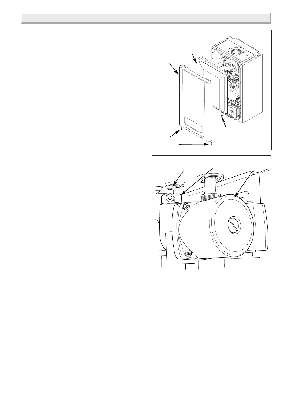
Diagram 11.2
CAP
AUTOMATIC
AIR VENT
PUMP
11507
Diagram 11.1
INNER
CASING
PANEL
CASING
PANEL
12353
SECURING
SCREWS
SECURING
SCREW (2)
Please ensure the "Benchmark" logbook is completed and left
with the user and the magnetic lighting instruction label is
placed on the surface of the boiler casing.
LPG CONVERSION - 30sxi only
NOTE: Steps 11.1 to 11.3 will need to be completed before the
appliance can be converted.
The 30sxi can be converted to run on LPG-Propane (G31).
This conversion should only be carried out by a competent
person.
During the conversion to Propane use of a suitable flue gas
analyser is necessary.
As an option a chargeable boiler only commissioning service
can be provided by Glow-worm Service by calling telephone No.
01773 828100.
Tools required to make the conversion are a 2mm Allen key and
an electricians screwdriver.
Ensure that the appliance supply pressure = 37mb.
(1) Access the gas valve.
(2) Refer to diagram 11.3 and turn the gas valve throttle fully
clockwise.
(3) Turn the throttle back anti-clockwise by 5
1
/
2
turns.
(4) Ensure that the gas analyser is set to the correct fuel
setting - Propane.
(5) Attach combustion analyser to the combustion test point.
See diagram 12.1.
(6) Unclip the controls fascia to reveal the service potentiometer
on the rear of the user interface. See diagram 12.7.
(7) Turn on the mains electrical supply and turn on the gas
service cock. Switch the boiler on.
(8) Ensure external controls are calling for heat. The boiler
should fire automatically.
(9) Using an electrical screwdriver, rotate the service
potentiometer to the mid point or 3 o’clock position. See
diagram 12.7. The fan speed should now reduce to minimum
and ‘12’ should be shown flashing on the digital display.
Check the CO
2
value. If necessary refer to diagram 11.3
and using a 2mm allen key carefully adjust the offset screw
until a CO
2
reading of 10.5% ± 0.2% is achieved. Turning
the offset screw clockwise increases the CO
2
reading.
(10) After setting combustion, rotate the service
potentiometer fully anti-clockwise so that the display
indicates the water temperature. Check that the CO
2
combustion remains between 9.8% and 10.8% CO
2
. Further
adjustment should not be necessary, however if required,
carefully adjust the gas valve throttle (see diagram 11.3)
until this is achieved.
(11) Remove analyser probe from the test point and replace the
cap. Refit the control panel.
(12) Fit the LPG conversion label supplied in the documentation
pack to the inner front panel alongside the data
label. Refit the inner door and outer door.
11 Commissioning
11.1 Preliminaries
A competent person in accordance with the current issue of
BS6798 should carry out commissioning.
NOTE: Remove the inner casing panel, see diagram 11.1.
Make sure that the system has been thoroughly flushed out with
cold water without the pump in place.
Refit the pump, fill the system with water, making sure that all
the air is properly vented from the system and pump, see
diagram 11.2.
Before operating the boiler check that all external controls are
calling for heat.