14 replacement of parts – Glow-worm 18-30sxi Range User Manual
Page 43
43
0020008155A
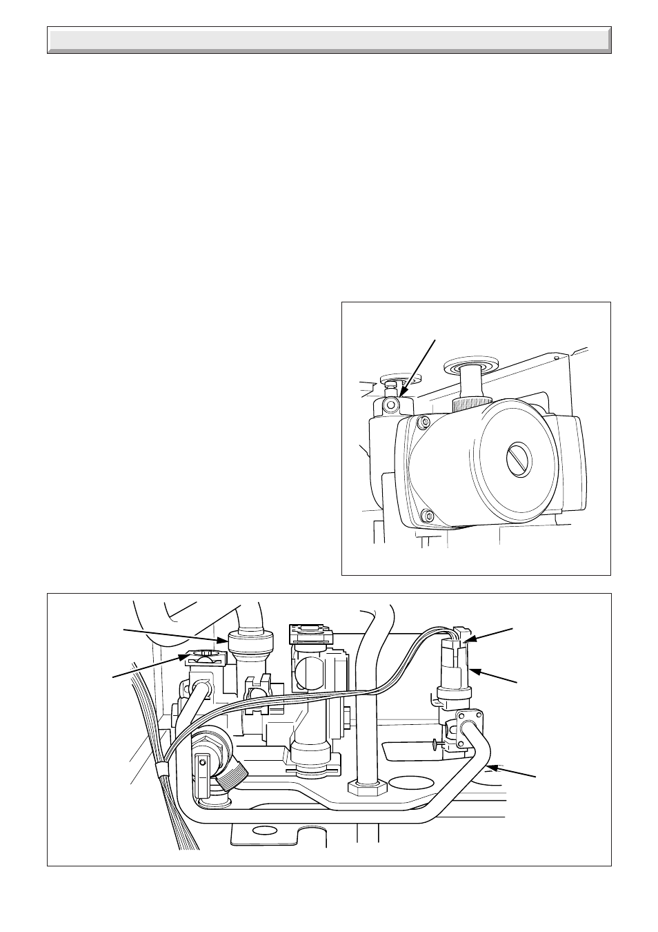
Diagram 14.15
LOW WATER
PRESSURE
SENSOR
BYPASS
TUBE
ELECTRICAL
LEAD AND
PLUG
AUTOMATIC
BYPASS
VALVE
FLOW PIPE
CONNECTOR
11605
14 Replacement of Parts
Diagram 14.14
AUTOMATIC
AIR VENT
14.19 Automatic Air Vent
For access, refer to section 14.1.
Refer to section 12.8 and drain the boiler heating circuit.
Refer to diagram 14.14.
Unscrew the automatic air vent.
Fit the new automatic air vent and ‘O’ ring ensuring the vent cap
is left loose.
Refill, vent and pressurise the boiler.
Check for leaks.
14.20 Low Water Pressure Sensor
For access, refer to section 14.1.
Refer to section 12.8 and drain the boiler heating circuit.
Refer to diagram 14.15.
Disconnect the electrical lead by pushing up retaining tab and
withdraw lead plug.
Remove the retaining clip to remove the low water pressure
sensor.
Fit the new low water pressure sensor. Refill vent and pressurise
the boiler.
Check for leaks.
14.21 Bypass Tube
For access, refer to section 14.1.
Refer to section 12.8 and drain the boiler heating circuit.
Refer to diagram 14.15.
Remove the retaining clips to remove the bypass tube.
Replace the bypass tube, refill, vent and pressurise the boiler.
Check for leaks.
11507
14.22 Automatic Bypass Valve
For access, refer to section 14.1.
Refer to section 12.8 and drain the boiler heating circuit.
Refer to diagram 14.15.
Remove the retaining clip to remove the bypass valve.
Replace the reduced pressure zone valve, refill, vent and
pressurise the boiler.
Check for leaks.
14.23 Central Heating Filter
Refer to section 12.7.