14 replacement of parts – Glow-worm 18-30sxi Range User Manual
Page 38
38
0020008155A
14 Replacement of Parts
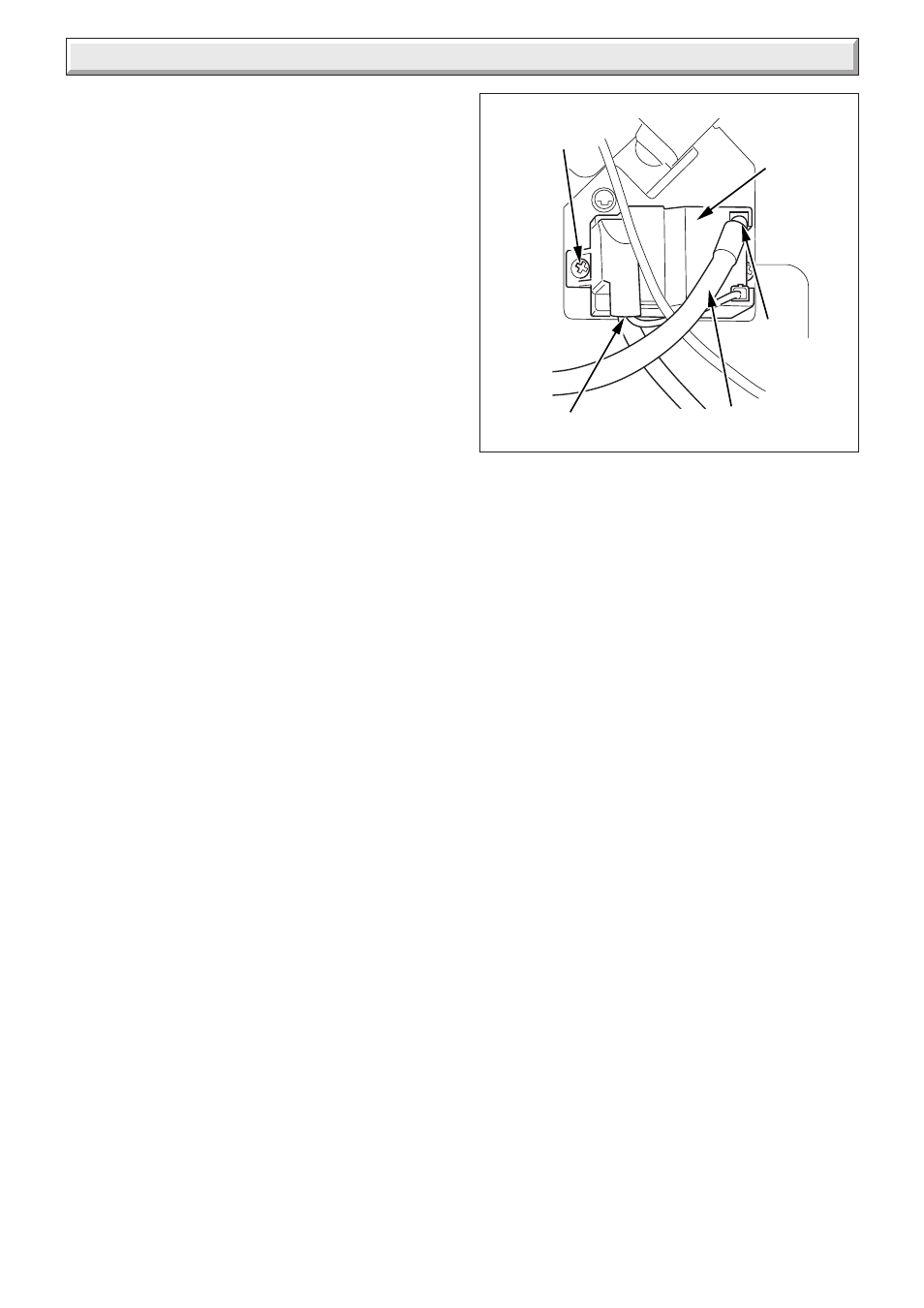
Diagram 14.1
IGNITER
UNIT
IGNITION LEAD
ELECTRICAL
CONNECTIONS
SECURING
SCREWS (2)
SPADE
CONNECTOR
14.1 Important Notes
When replacing a part on this appliance, use only spare parts
that you can be assured conform to the safety and performance
specification that we require. Do not use reconditioned or copy
parts that have not been clearly authorised by Glow-worm.
Replacement of parts must be carried out by a competent
person.
Before replacing any parts the boiler should be isolated from the
mains electric supply and the gas should be turned off at the
service cock on the boiler, see diagram 7.1.
Unless stated otherwise parts are replaced in the reverse order
to removal.
After replacing any parts always test for gas soundness and if
necessary carry out functional test of the controls.
For replacement of parts the front casing and the inner casing
panel of the boiler will need to be removed. To remove undo the
two screws on the underside of the front casing and lift off. Undo
the two screws on the front of the inner front panel and lift off.
The side panels can be hinged sideways to aid replacement of
parts.
Undo and remove the three screws securing each side panel to
the boiler, two at the front and one at the top.
14.2 Spark Electrode
For access, refer to section 14.1.
Remove the spark plug lead, earth lead and two securing
screws. Withdraw the spark electrode carefully from the
combustion chamber, see diagram 12.2.
14.3 Igniter Unit
For access, refer to section 14.1.
Remove ignition lead and electrical connections, then remove
igniter unit by removing two securing screws, see diagram 14.1.
14.4 Ignition Lead
For access, refer to section 14.1.
Refer to diagram 12.5.
Pull the spark plug style connector off the spark electrode and
the spade connector connected to the igniter unit, see diagram
14.1.
11492