10 electrical connections – Glow-worm 18-30sxi Range User Manual
Page 25
25
0020008155A
10 Electrical Connections
WARNING: This appliance must be wired in accordance with
these instructions. Any fault arising from incorrect wiring cannot
be put right under the terms of the Glow-worm guarantee.
All system components must be of an approved type.
Electrical components have been tested to meet the equivalent
requirements of the BEAB.
Connection of the whole electrical system and any heating
system controls to the electrical supply must be through a
common isolator.
Isolation should preferably be by a double pole switched fused
spur box having a minimum contact separation of 3mm on each
pole. The fused spur box should be readily accessible and
preferably adjacent to the boiler. It should be identified as to its
use.
A fused three pin plug and shuttered socket outlet may be used
instead of a fused spur box provided that:
a) They are not used in a room containing a fixed bath or
shower.
b) Both the plug and socket comply with the current issue of
BS1363.
The mains electrical supply must be maintained at all times in
order to provide domestic hot water.
Do not interrupt the mains supply with a time switch or
programmer.
WARNING: UNDER NO CIRCUMSTANCES MUST ANY
MAINS VOLTAGE BE APPLIED TO ANY OF THE TERMINALS
ON THE VOLTAGE FREE HEATING CONTROLS
CONNECTION PLUG.
10.1 Mains Cable
IMPORTANT: If a replacement supply cable is required it must
be purchased. Part No. S1008600.
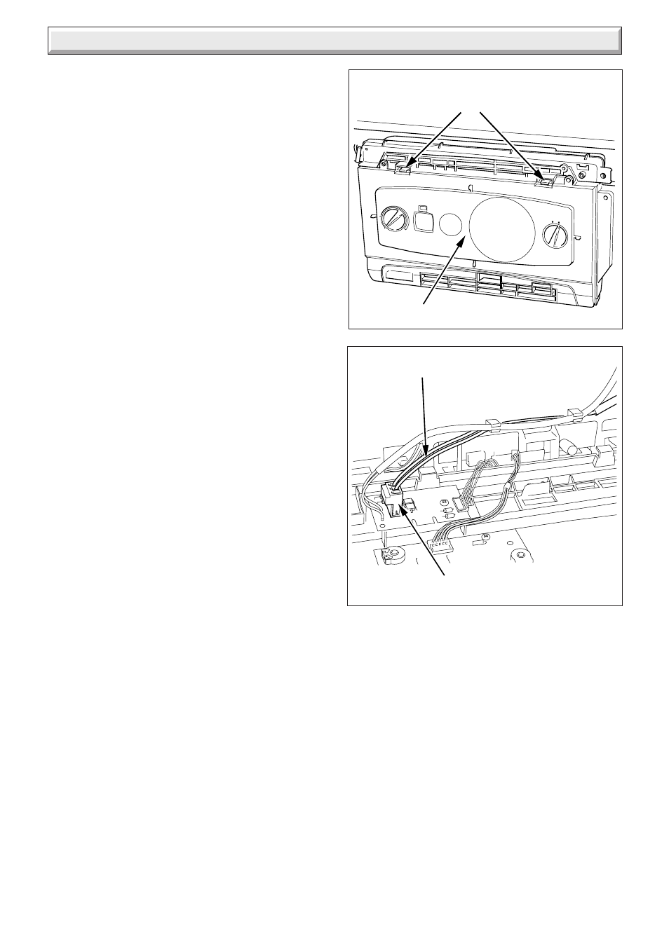
10.2 External controls (Mains Voltage)
Gain access to the 230V interface by unclipping the controls
fascia and hinging forward, see diagram 10.1.
Remove the red link from the mains voltage heating controls
connection plug and connect as shown in diagrams 10.2 & 10.3,
then route the external control cable as shown on diagram 10.2.
Close the fascia panel and open the rear cover of control panel,
see diagram 10.4.
Secure the external control cable in the strain relief, see
diagram 10.4.
Thread the external control cable through rear of the control
panel where the other cables exit, see diagram 10.4.
Close rear cover of control panel.
External control should be fitted in accordance with the rules in
force.
Refer to wiring diagram in Section 13.
Diagram 10.2
PLUG
EXTERNAL CONTROLS
CABLE (MAINS VOLTAGE)
Diagram 10.1
RETAINING
LATCHES
11505
11408
CONTROLS FASCIA