14 replacement of parts – Glow-worm 18-30sxi Range User Manual
Page 46
46
0020008155A
14 Replacement of Parts
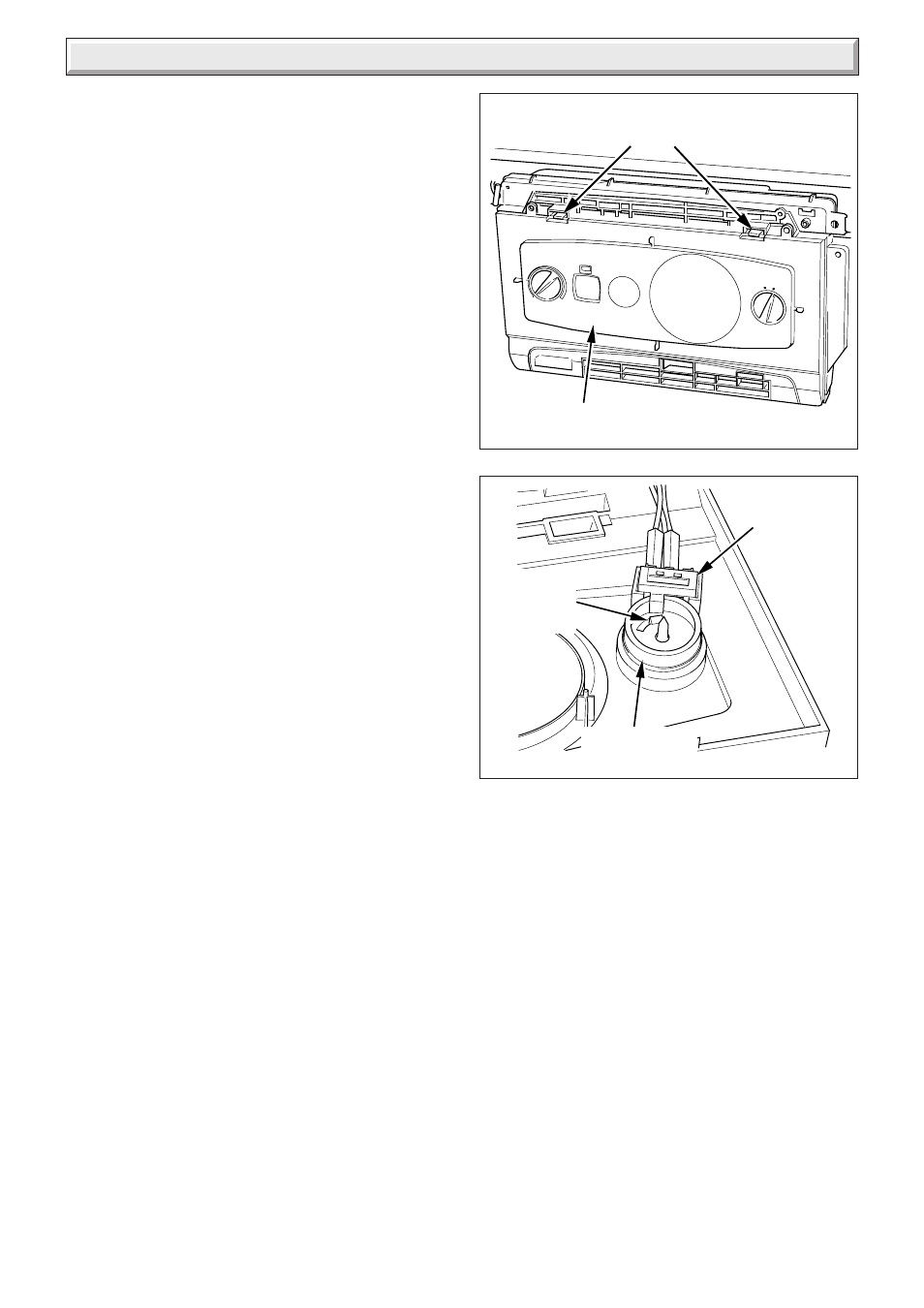
Diagram 14.20
RETAINING
LATCHES
11505
Diagram 14.21
MAINS RESET
SWITCH
KNOB
RETAINING
CLIPS
MAINS RESET
KNOB
14.29 Access to Switches and User Interface
For access, refer to section 14.1.
Release the front of the fascia by carefully prising up the two
retaining latches, see diagram 14.20.
Do not allow the front of the controls fascia to swing down and
be loosely held by the electrical connections to the mainsreset
switch, user interface and programmer. Either remove the
connections or support the fascia.
14.30 Mains Reset Switch
Refer to section 14.29 for access and diagram 14.21.
Remove the switch retaining screw.
Remove switch from housing.
Remove electrical leads.
14.31 Mains Reset Knob
Refer to section 14.29 for access.
Remove actuator by springing back retaining clips, see diagram
14.21.
Spring back knob retaining clips and push knob out from the
back.
14.32 User Interface
Refer to section 14.29 for access and diagram 14.23.
Remove electrical plug.
Remove the two securing screws.
Withdraw the board.
When replacing the board refer to instructions supplied with
replacement PCB on setting it up.
14.33 Main PCB
For access, refer to section 14.1.
Hinge down the control box.
Remove three TORX screws and unhook the rear panel.
Remove the electrical connections to the PCB.
Prise back the two PCB retaining clips and withdraw the PCB.
When refitting the rear panel ensure the leads are not trapped.
14.34 Control Box
For access, refer to section 14.33.
Remove relevant plugs and connectors, refer to wiring diagram
13.2.
Withdraw grommets and leads so they are hanging loose.
Unthread the retaining strap and remove the control box by
drawing it outwards away from its retaining slots, see diagram
14.22.
CONTROLS
FASCIA