14 replacement of parts – Glow-worm 18-30sxi Range User Manual
Page 39
39
0020008155A
14 Replacement of Parts
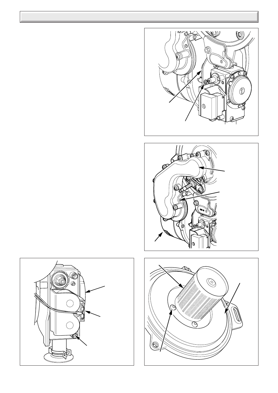
Diagram 14.2
ELECTRICAL
PLUG
GAS
VALVE
PRESSURE
TEST POINT
Diagram 14.5
SECURING
SCREW (4)
BURNER
INSULATION
14.5 Gas Valve
For access, refer to section 14.1.
Remove the electrical plug from the gas valve, see diagram
14.2.
Refer to section 12.3 for removal of the fan, gas valve and
burner assembly.
Before removing the gas valve note its position on the fan.
Remove the three securing screws, which fix the gas valve,
plastic swirl plate to the venturi on the fan.
Remove the gas valve.
Remove the flexible gas supply pipe from the gas valve.
When refitting the gas valve take care as it can be fitted more
than one way.
After assembly test for gas soundness and purge in accordance
with the current issue of BS6891 or in IE, the current edition of
I.S.813 "Domestic Gas Installations".
14.6 Fan
For access, refer to section 14.1.
Refer to section 12.3 for removal of the fan gas valve and burner
assembly.
Remove the gas valve as described in the relevant parts of
section 14.5.
Remove the venturi plate secured with four screws and remove
the two screws securing the fan to the gas manifold, see
diagram 14.3.
Check the gasket and replace if necessary.
NOTE: The 30sxi fan is secured through an extension piece
with two securing screws, check and replace any seals or
gaskets if necessary.
14.7 Burner
NOTE: THE BURNER WILL REQUIRE A NEW GASKET
WHEN REFITTED.
For access, refer to section 14.1.
Refer to section 12.3 for removal of the fan, gas valve and
burner assembly.
Remove the four screws that secure the burner, see diagram
14.5.
12402
11487
Diagram 14.4
Diagram 14.3
SECURING
SCREW (2)
SECURING
SCREW (3)
VENTURI
PLATE
FAN
GAS
MANIFOLD
11486
11485