14 replacement of parts – Glow-worm 18-30sxi Range User Manual
Page 40
40
0020008155A
14 Replacement of Parts
HEAT
EXCHANGER
Diagram 14.6
11412
SECURING SCREW
WASHER
REAR
INSULATION
14.8 Front Insulation
For access, refer to section 14.1.
Refer to section 12.3 for removal of the fan, gas valve and
burner assembly.
Remove burner as described in section 14.7.
Remove spark electrode, see section 14.2.
NOTE: THE BURNER WILL REQUIRE A NEW GASKET
WHEN REFITTED.
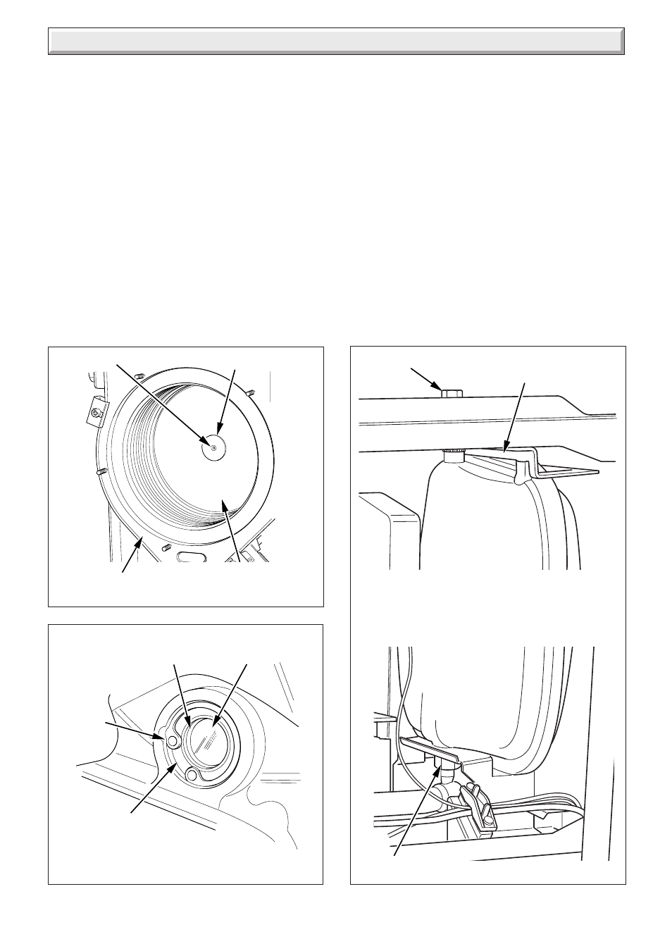
14.9 Rear Insulation
For access, refer to section 14.1.
Refer to section 12.3 for removal of the fan, gas valve and
burner assembly.
Remove securing screw and washer in the centre of the
insulation and withdraw insulation, see diagram 14.6.
14.10 Viewing Window
For access, refer to section 14.1.
Refer to diagram 14.7.
Remove circlip.
Remove steel washer.
Remove glass.
Remove fibre washer.
Replace in reverse order.
Diagram 14.7
CIRCLIP
GLASS
STEEL
WASHER
FIBRE
WASHER
11413
Diagram 14.8
SECURING
BOLT
COUPLING
UPPER SUPPORT
BRACKET
EXPANSION
VESSEL
11488
11489
- 12-38hxi Range (44 pages)
- 23c (44 pages)
- 24-38CXI Range (52 pages)
- 30ci Plus (56 pages)
- BBU 45/4 (32 pages)
- BBU 54/4 (32 pages)
- Betacom C (68 pages)
- Betacom2 (8 pages)
- Betacom2 (20 pages)
- Betacom2 (56 pages)
- Black Beauty 4 (20 pages)
- Chatsworth 4 (24 pages)
- Clearly Heat Recovery (20 pages)
- Clearly Heat Recovery (32 pages)
- Clearly Heat Pumps Envirosorb3 (28 pages)
- Clearly Heat Pumps Envirosorb2 (44 pages)
- Clearly Heat Pumps 7kW (44 pages)
- Clearly Heat Pumps 5kW (28 pages)
- Clearly Heat Pump 5kW (16 pages)
- Clearly Heat Pump 5 kW (32 pages)
- Clearly Heat Pump - Buffer Vessel (10 pages)
- Clearly Heat Pumps - Standalone Module System (40 pages)
- Clearly Heat Pumps - Standalone System (28 pages)
- Clearly Hybrid - Universal Module (20 pages)
- Clearly Hybrid - Universal Module System (36 pages)
- Clearly Hybrid - Compact Hydraulic Module (12 pages)
- Clearly Hybrid - Compact System (36 pages)
- Clearly Hybrid - Compact Hydraulic Module HB (16 pages)
- Clearly Hybrid - Back-up Module System (40 pages)
- Clearly Solar System Hydraulics (28 pages)
- Clearly Solar System (28 pages)
- Clearly Solar Controller (28 pages)
- Clearly Solar Horizontal On-Roof Collector (16 pages)
- Clearly Solar Vertical On-Roof Collector (16 pages)
- Clearly Solar Cylinders (32 pages)
- Clearly Solar - A-Frame (28 pages)
- Clearly Solar Horizontal In-Roof Collector (32 pages)
- Clearly Solar Vertical In-Roof Collector (44 pages)
- Clearly Solar Collector Container (8 pages)
- Climapro 1 (12 pages)
- Climapro2 RF (16 pages)
- Climapro2 RF (24 pages)
- Climapro2 RF (36 pages)
- Climapro2 RF (32 pages)