ENMET ISA-60M with MRI-5175 User Manual
Page 9
ISA-60M
ENMET Corporation
6
3.2 Wiring ISA-60M to MRI-5175
Wiring for the
MRI-5175
alarm, relay contacts and 4-20mA outputs may be routed through one of the two enclosure punch-
outs on the side or bottom of the enclosure. See Figure 1. Follow state and local guidelines when selecting appropriate strain
relief, conduit and wiring.
Remote Sensor: Each must be connected to a 4-20mA input inside the
ISA-60M
. UL listed type CM, PLTC or TC cable shall
be used for wiring between the
MRI-5175
and the
ISA-60M
control panel. Three conductor, 18 gauge
shielded
wiring for
runs up to 1000 feet. For 500 feet or shorter
shielded
wiring runs, 20 gauge wiring is acceptable. The supplied strain reliefs
are rated for cable with an OD between 0.20 – 0.35 inches. Refer to Section 7.0 for typical wiring information.
C
AUTION
:
Be careful not to scratch or otherwise damage the internal metallic coating of the
MRI-5175
during
installation.
Table 1: Wiring ISA-60M
to
MRI-5175
ISA-60M
MRI-5175
Channel 1, J16
+24V (1)
GND (2)
mA (3)
Power
Ground
Signal
Channel 1, J4
+24V
GND
mA
*
Channel 2, J18
+24V
GND
mA
Power
Ground
Signal
Channel 2, J4
+24V
GND
mA
*
Channel 3, J19
+24V
GND
mA
Power
Ground
Signal
Channel 3, J4
+24V
GND
mA
*
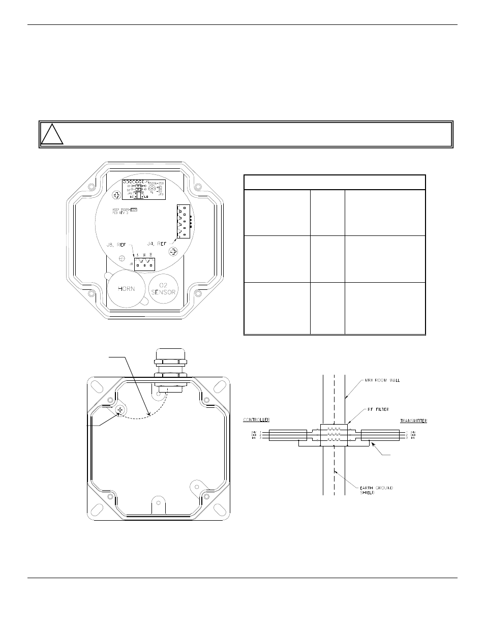
*Shielding wire to Ground Screw of
MRI-5175
Ground Screw
Figure 4: MRI-5175 Ground for Shielded Cable
!
MRI-5175 Lid, interior view
(Optional)
D–
D+
mA
GND
24V
J4
Ground Screw
MRI-5175 enclosure, interior view
Shielding wire to Ground Screw
of MRI-5175 enclosure
Shield Wire