0 installation – ENMET ISA-60M with MRI-5175 User Manual
Page 8
ISA-60M
ENMET Corporation
5
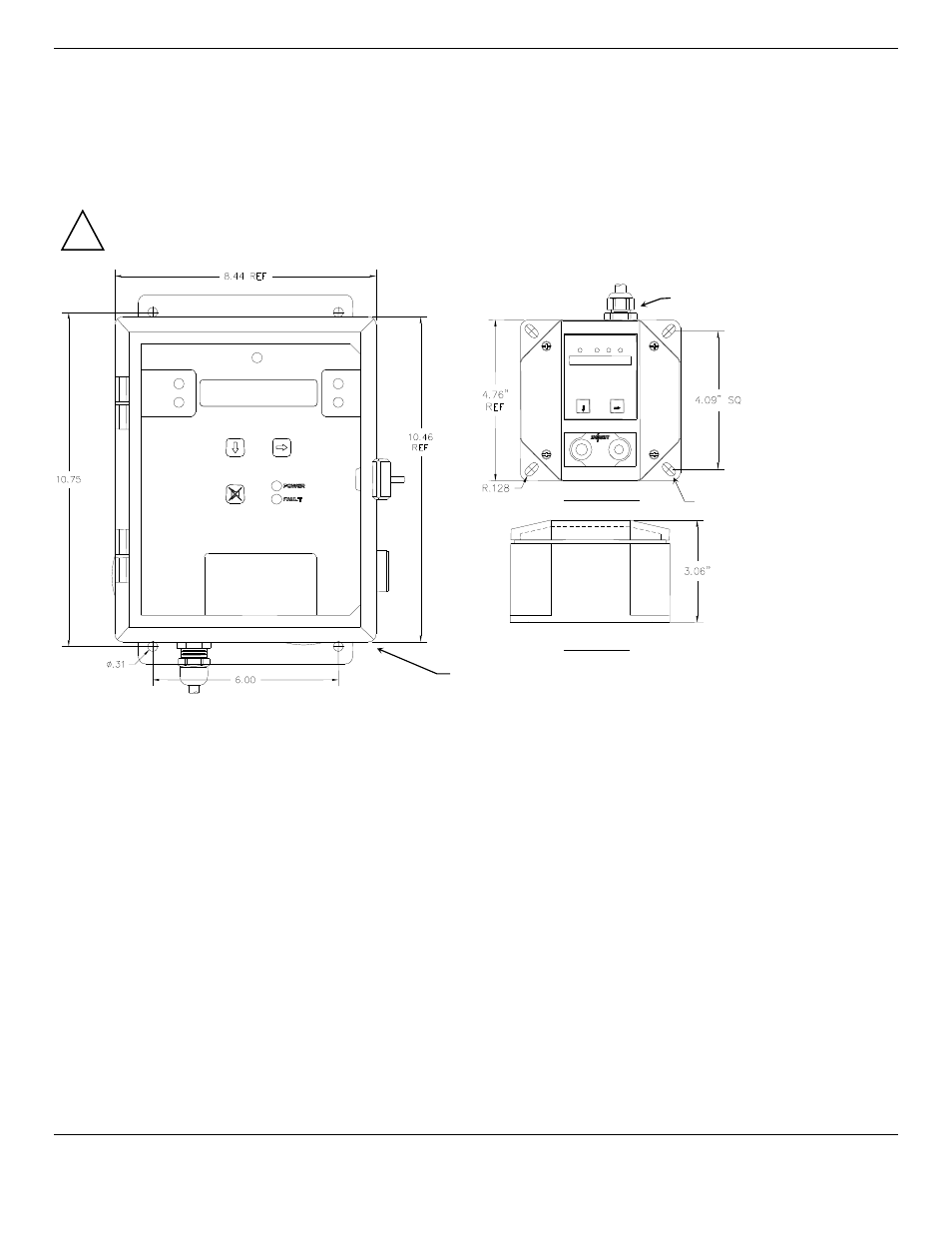
3.0 Installation
3.1 Mounting of Instrument
Mount the
ISA-60M
and
MRI-5175
instrument on an appropriate vertical surface using the mounting flanges provided. Avoid
areas with excessive vibration or temperature extremes. See Figure 3.
It is recommended to use #8 drywall anchors and screws for mounting the
ISA-60M
and
MRI-5175
to a drywall/sheetrock
surface.
Non-magnetic mounting hardware is required for control panels located in the magnet room.
Dimensions are in inches.
Figure 3: ISA-60M
C
ONTROL
&
MRI-5175
R
EMOTE
S
ENSOR
Mounting Dimensions
N
OTE
: Remote Sensor, Each must be connected to a 4-20mA input inside the
ISA-60M
. UL listed type CM, PLTC or TC cable
shall be used for wiring between the
MRI-5175
and the
ISA-60M
control panel. Three conductor, 18 gauge
shielded
wiring
for runs up to 1000 feet. For 500 feet or shorter wiring runs, 20 gauge
shielded
wiring is acceptable. The supplied strain
reliefs are rated for cable with an OD between 0.20 – 0.35 inches.
Refer to Section 7 for Technical Instillation Data.
Mounting Holes
0.31” dia. 4 places
!
Side View
Mounting Holes R 0.28” dia.
4 places
Menu
Select
SN: -XXXX
Front View
Typical location of Strain Relief