3 power supply, 5 initial calibration – ENMET ISA-60M with MRI-5175 User Manual
Page 12
ISA-60M
ENMET Corporation
9
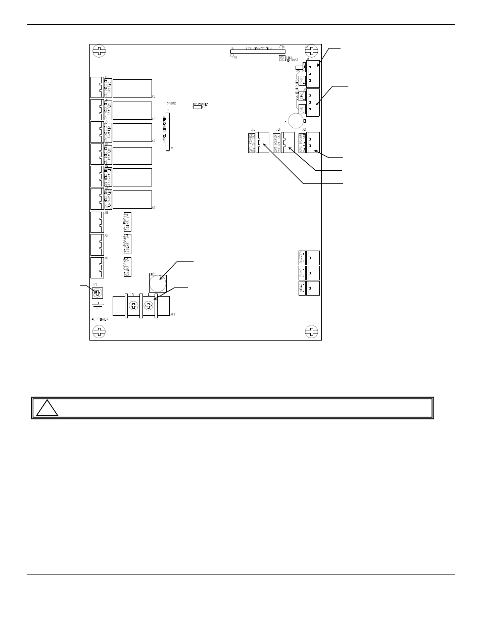
Figure 5: ISA-60M Relay and Input and Output Terminals
3.3 Power Supply
The input power can vary from 100 to 240
V
AC
, 50/60 Hz. Mains power should be connected to the Power Input Terminal J23
and the ground screw J21. See Figure 5 for location.
W
ARNING
:
Continuous gas detection and alarm systems become inoperative upon loss of primary power.
Upon supplying power to the
ISA-60M
:
The green power on LED is lit.
The display backlight is lit, and instrument will step through a start-up sequence: unit serial number, software revision
and gases monitored may be shown on the display.
The instrument may go into alarm briefly, but the sensors stabilize quickly. If the instrument persists in alarm, acknowledge the
alarm by pressing the
A
UDIO
D
EFEAT
/A
LARM
A
CKNOWLEDGE
switch. If alarm persists longer than 30 minutes, call
ENMET
customer service personnel.
Mains power line is fused for power supply protection. Fuse is 5
x
20mm, 0.630Amp is located in
FH2
, see Figure 5
3.5 Initial Calibration
All instruments are calibrated at the factory. You may, if a calibration kit is available, calibrate the
MRI-5175
3 – 4 hours after installation. See Section 5.0, Maintenance, for calibration instructions.
!
Relay 1
Channel 1
Alarm 1
Relay 2
Channel 2
Alarm 1
Relay 3
Channel 3
Alarm 1
Relay 4
Channel 4
Alarm 1
Relay 5
Channel 1-4
Alarm 2
Relay 6
Ch 1-4 / System
Fault
J16 Detector Primary
Channel 1
J18 Connector
4-20mA Input
Channel 2
J19 Connector
4-20mA Input
Channel 3
Connector 2 (J4)
Channel 3 & 4
4-20mA Output
Connector 1 (J7)
Channel 1 & 2
4-20mA Output
Connector RS485
Connector RS232
Connector RS485
Power Input, Terminal J23
L-Line
N-Neutral
Ground Screw J21
Fuse Holder FH2