ENMET ISA-60M with MRI-5175 User Manual
Page 7
ISA-60M
ENMET Corporation
4
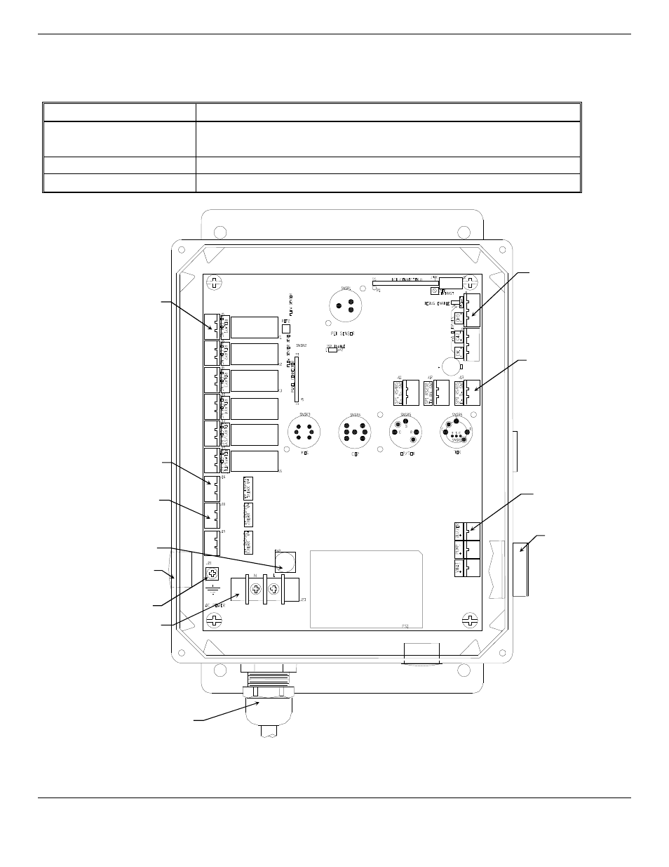
2.3 Circuit Board Features
The Display Panel is hinged on the left and is released by unscrewing the 2 philips screws located in the top and bottom right
corners. After releasing the panel, it is swung to the left, exposing the interior of the enclosure. The Circuit Board is mounted
on a plate at the back surface of the enclosure interior. Features are shown in Figure 2.
Feature
Description
Relay Terminals
This group of terminals is located at the left side of the Circuit Board.
For the contacts for each of four alarm relays, and for the contacts of a fault relay.
Output Terminals
There are two for each of the 4-20 mA outputs.
Figure 2: ISA-60M
Interior Features
Power Input
Terminal J23
Audio
Alarm
Relay Terminals
(6 places)
Aux Terminals
Optional (2 places)
Primary Detector
Channel 1
Horn Terminal
4 – 20mA Output
Terminals
4 outputs
2 connectors
Fuse Holder
Digital Communication
Terminals (3 types)
Ground Screw J21
Hole Plugs
(2 places)
Strain Relief