Multi format imager assembly – Da-Lite Multi Format Imager User Manual
Page 4
4
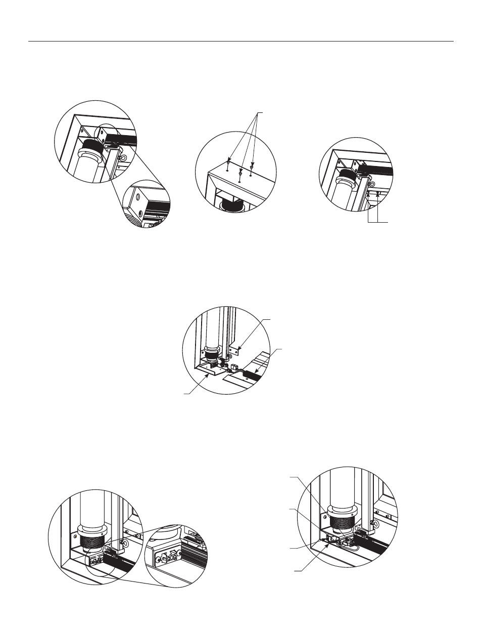
Tighten Set Screws
Until Front Surfaces
Are Flush
Fasten Screws
Through Top Frame
Assembly Into
Connecting Bracket
Small L
Bracket
Aluminum Guide
Channel
Large L
Bracket
Plug Motor Power In
Route Power
Cable Behind
Motor Bracket
Tuck Excess Wire
Underneath Motor
Bracket
Tuck RJ-45 Coupler
Underneath
Motor Bracket
Data Cable
From Motor Head
4. Fasten (3) #10 x .375" long button head screws through top of frame into the corner connector bracket. See Figure 5.
Tighten two set screws on flat "L" bracket to line up the front faces as shown in Figure 6.
5. Assemble bottom side of frame to left frame. The large metal L bracket will slide into the aluminum extrusion while the small
L bracket will slide into the aluminum channel. When sliding the bracket into the bottom frame assembly, guide the slat roller
carriage into the bottom aluminum guide channel. See Figure 7.
6. Route the two cable assemblies around motor bracket and plug the 3 wire male connector into the 3 wire female connector
on the motor bracket. The motor will have a gray data cable with an RJ-45 connector on the end coming out of the head of the
motor. Plug this end into the RJ-45 coupler. Tuck the RJ-45 coupler underneath motor bracket securely to prevent entanglement
as shown in Figure 9.
Multi Format Imager Assembly
Figure 4
Figure 5
Figure 6
Figure 7
Figure 8
Figure 9