American Energy Systems MagnuM 7500 User Manual
Page 35
35
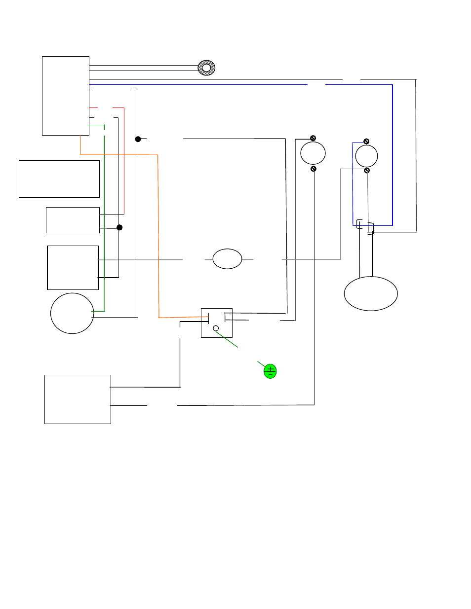
Magnum 6500 Wiring Diagram
(See figure 17 for detailed position for wire harness)
The High limit control is pre-set and does not need to be adjusted. If the furnace is overheating
consult your HVAC installer for proper duct installation, pressures and sizing.
The fan limit control heat settings are pre-set and do not need to be changed. If the room fan is cycling
often consult your HVAC contractor for proper duct pressure setting.
\
Circuit
Board
Control
AES #
MF3594 is
used on 6500
2 wire low voltage thermostat
Power Cord
Receptacle
showing
back of plug
Green
Ground
Exhaust Motor
AES # MF3650
Auger Gear
Motor
AES # MF3573 on
6500 unit
Blower
1240 cfm
AES # CF24
white
Black from blower fan to
power receptacle
Fan
Gray
High Limit
sensor
Fan limit
sensor
power
Blue
Proof of
fire
sensor
110 deg
White neutral
White neutral
Red
Black
Green
Orange
AES # MF3537
white
Black
Vacuum
pressure switch
Gray
Black
200 deg. High
limit snap disk
A 200-degree high limit
control has to be installed
in the primary furnace
duct work below the
Magnum 7500 hot air
outlet in a supplementary
furnace installation only.
MF3650 2-speed exhaust
blower to be wired using
the white and black leads
red lead is not used.