Appendix b, Video adapter board, Overview product description – ADLINK CoreModule 720 User Manual
Page 59: Appendix b video adapter board, Overview, Product description
CoreModule 720
Reference Manual
53
Appendix B
Video Adapter Board
Overview
This appendix describes the functionality and features of the CoreModule 720 video adapter board and
presents an illustration of the connector locations and the board dimensions as well as the pin-out table for
the non-standard VGA interface on the adapter.
Product Description
The video adapter board enables VGA functionality on the CoreModule 720, converting digital RGB input
from the module’s SDVO port to analog RGB output through an on-board display controller. The display
controller accepts and decodes digital graphics, high-speed AC-coupled serial differential input from the
SDVO port on the module and encodes and transmits analog RGB output to a non-standard VGA interface
header on the adapter board. Simply connect an SDVO cable from the CoreModule 720 to the SDVO
connector on the adapter board and a VGA cable from the adapter board to a VGA display.
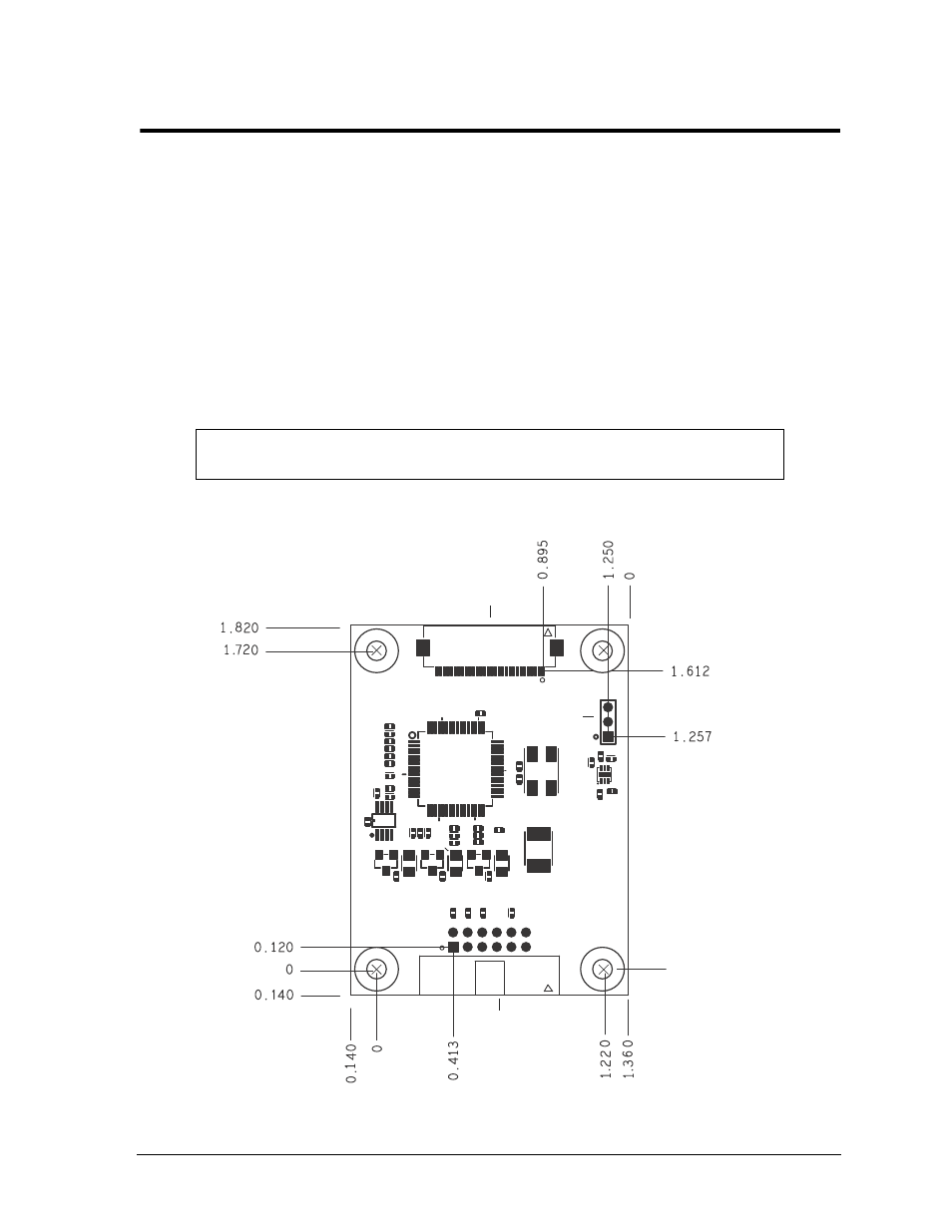
Figure B-1. Adapter Board Headers and Dimensions (Top Side)
CAUTION
Make sure the JP1 jumper is installed on pins 2-3. Black squares on the
headers of
indicate pin 1. Mounting hole sizes = 106 MILS.
J1
JP1
J2
Mounting Hole (4)
and VGA_GND
CM720_V
id_Aptr_a
Key:
J1 - SDVO input
J2 - VGA output
JP1 - Voltage Select
Note: All dimensions
are given in inches.