I2c interface system fan, Table 3-18, I2c interface pin signals (j6) – ADLINK CoreModule 720 User Manual
Page 38: Table 3-19, System fan pin signals (j21), C interface, System fan
Chapter 3
Hardware
32
Reference Manual
CoreModule 720
I
2
C Interface
The CoreModule 720 provides a single-channel I2C interface, which conforms to version 2.1 of the I2C bus
specification. The I2C controller resides on the EG20T PCH and operates as a master or slave device,
supporting a multi-master bus. The following list highlights the features of the I2C bus interface.
Supports delay processing of data read/write operation
Supports master and slave devices
Supports SCL generation when acting as a clock master
Supports multiple masters
Supports Low-Speed BusClock as its clock source and generates an SCL clock based on the set
value of the I2CBC register
Supports 32-byte buffering
Provides a function that generates time out in buffer mode
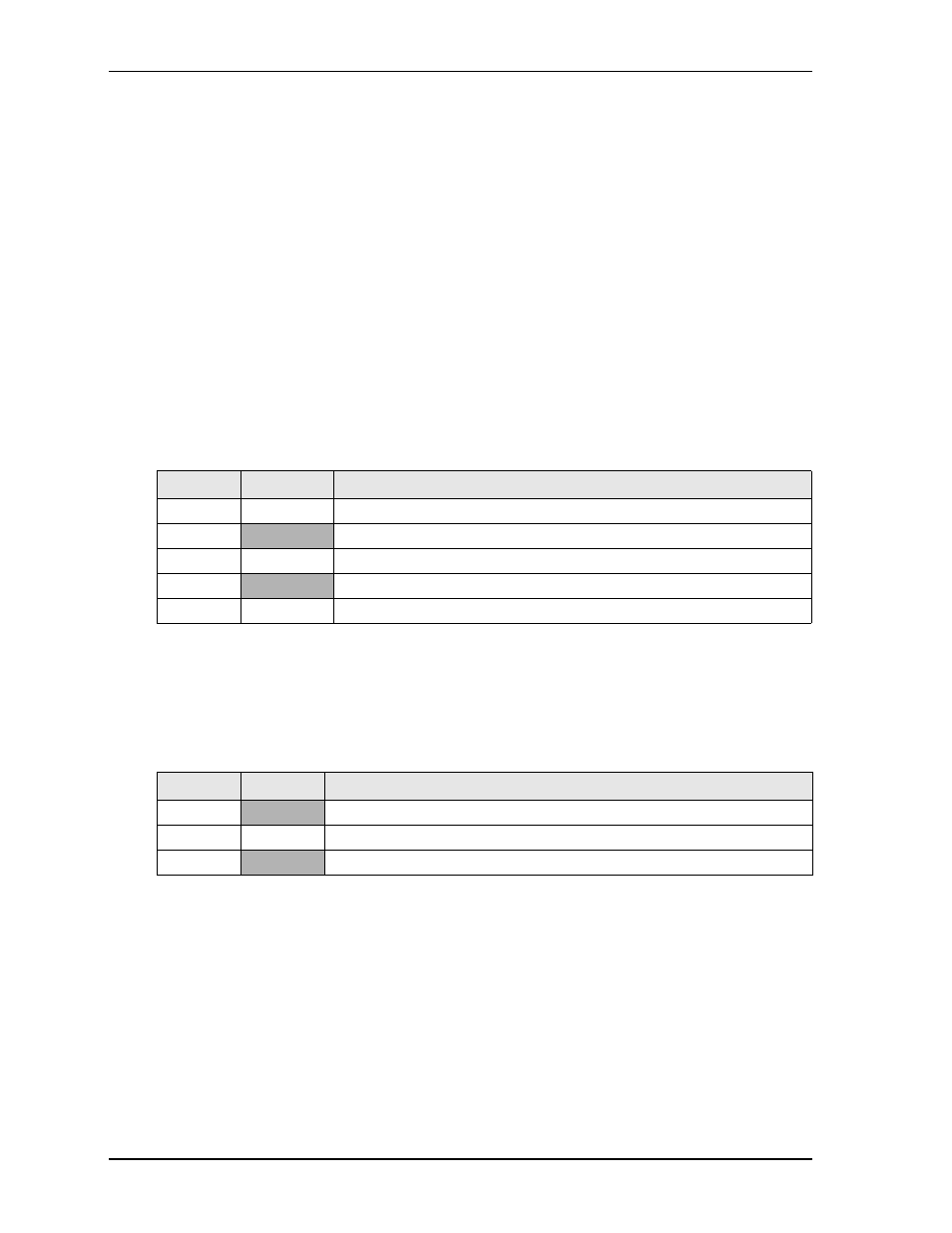
defines the pin signals of the I
2
C bus interface, which provides a 5-pin, single-row header with
0.079" (2mm) pitch.
Note: The shaded table cells denote power or ground.
System Fan
lists the pin signals of the System Fan header, which provides a single row of 3 pins with 0.079"
(2mm) pitch.
Note: The shaded table cells denote power or ground.
Table 3-18. I
2
C Interface Pin Signals (J6)
Pin #
Signal
Description
1
I2C_CLK
I2C Clock
2
GND
Ground
3
I2C_DATA
I2C Data
4
+3.3V
+3.3 volts power
5
NC
Not Connected
Table 3-19. System Fan Pin Signals (J21)
Pin #
Signal
Description
1
+V_FAN
+5.0 volts DC +/- 5%
2
NC
Not Connected
3
GND Ground