Jumper header definitions, Table 2-3, Jumper settings – ADLINK CoreModule 720 User Manual
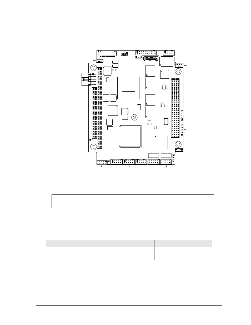
Page 19: Figure 2-6
Chapter 2
Product Overview
CoreModule 720
Reference Manual
13
Figure 2-6. Header, Connector, and Socket Locations (Top Side)
Jumper Header Definitions
describes the jumper headers shown in
. Both jumper headers provide 0.079" (2mm)
pitch.
NOTE
Black square pins on headers and connectors represent pin 1. Black square pins on
right-angle headers represent pin 2 in top-side views and pin 1 in bottom-side views.
Table 2-3. Jumper Settings
Jumper Header
Installed
Removed
JP1 – Clear CMOS
Enable
Disable (Default)
JP3 – LVDS Voltage Selection
Enable +3.3V (1-2) (Default)
Enable +5V (2-3)
CM720_T
op_Conn_a
Key:
J1 - LPC
J3 - GPIO
J4 - CAN
J5 - SD Memory Socket - Bottom
J6 - I2C
J7 - SATA0
J8 - Ethernet - Gigabit
J9 - Ethernet LED - Gigabit
J10 - Serial 1 - COM 0
J11 - Serial 2 - COM 1, 2, 3
J12 - USB 0, 1
J13 - USB 4, 5
J14 - USB 2, 3
J15 - SDVO
J17 - PC/104-Plus
J18 - PC/104
J19 - Power
J20 - Battery
J21 - Fan
J22 - Utility
J23 - LVDS
J24 - SMBus
JP1 - RTC Reset
(See jumper table)
JP3 - LVDS Voltage Select
(See jumper table)
J21
J13
J20
J12
J10
J14
J11
J7
DC
AB
ABCD
JP3
JP1
J23
J6
J22
J24
J3
J19
J9
J1
J8
J15
J4
J17
J18