System management bus (smbus) can bus interface, Table 3-15, Smbus reserved addresses – ADLINK CoreModule 720 User Manual
Page 37: Table 3-16, Smbus pin signals (j24), Table 3-17, Can interface pin signals (j4), System management bus (smbus), Can bus interface
Chapter 3
Hardware
CoreModule 720
Reference Manual
31
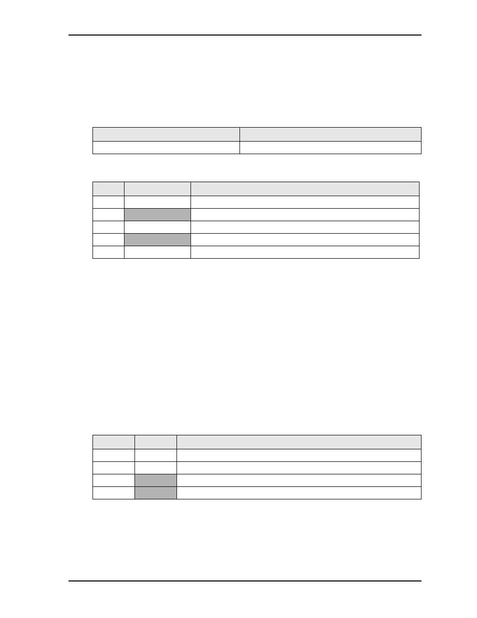
System Management Bus (SMBus)
The E6XXT chip contains a host SMBus port. The host port allows the CPU access to the SMBus slave
through header, J24. The SMBus slave includes the CPU Temperature Monitor.
name and corresponding reserved binary address on the SMBus.
lists the SMBus pin signals on 5
pins, 1 row, 0.079" (2mm) pitch.
Note: The shaded table cells denote power or ground. The * symbol indicates the signal is Active Low.
CAN Bus Interface
The CAN controller resides in the PCH and performs communication in accordance with the Bosch CAN
Protocol version 2.0B Active (standard and extended formats.) The CAN transceiver connects the CAN
controller to the CAN bus, and transmits and receives CAN signals to and from the CAN header (J4). The
CAN interface delivers CAN signals used for automotive, industrial automation, and medical scanning and
imaging applications. The following list describes some of the features of the CAN Bus Interface.
+/- 12 kV ESD protection
Low-current Standby mode with bus wake up: 5 A typical
Bus-fault protection of -27V to 40V
Over-temperature shutdown
defines the pin signals of the CAN bus interface, which provides a 4-pin, single-row header with
0.079" (2mm) pitch.
Note: The shaded table cells denote power or ground.
Table 3-15. SMBus Reserved Addresses
Component
Address (Hex)
CPU Temperature Monitor
4C
Table 3-16. SMBus Pin Signals (J24)
Pin #
Signal
Description
1
SMB_CLK
SMBus Clock
2
GND
Ground
3
SMB_DATA
SMBus Data
4
VSM
+3.3V standby voltage
5
SMB_ALERT*
SMBus Alert
Table 3-17. CAN Interface Pin Signals (J4)
Pin #
Signal
Description
1
CAN_L
Dominant Low
2
CAN_H
Dominant High
3
+5V
+5 volts power
4
GND
Ground