Figure 2-3, Component locations (top side), Figure 2-4 – ADLINK CoreModule 720 User Manual
Page 16: Component locations (bottom side), Figures 2-3, Side [see
Chapter 2
Product Overview
10
Reference Manual
CoreModule 720
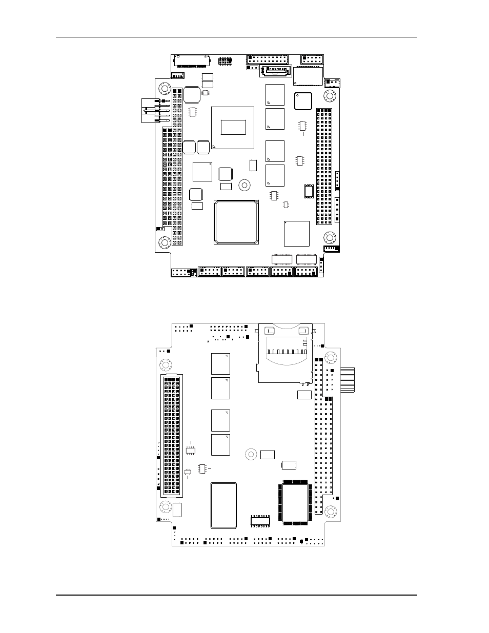
Figure 2-3. Component Locations (Top Side)
Figure 2-4. Component Locations (Bottom Side)
CM720_T
op_Comp_a
Key:
U1 - CPU
U2 - DDR2 SDRAM - 1
U3 - DDR2 SDRAM - 1
U4 - DDR2 SDRAM - 1
U5 - DDR2 SDRAM - 1
U10 - PCH
U15 - Gigabit Ethernet Controller
U16 - Ethernet EEPROM
U18 - PCIe to PCI Bridge
U21 - RS-232 Transceiver - COM0
U22 - RS-232 Transceiver - COM1-3
U31 - SPI Flash - BIOS
U33 - Temperature Monitor
U35 - Thermal Regulator - SSD
T1 - Gigabit Ethernet Transformer
U16
U31
U15
U3
U2
U4
U18
U22
U21
U35
U10
U5
T1
U1
U33
CM720_Bottom_Comp_a
Key:
U6 - DDR2 SDRAM - 2
U7 - DDR2 SDRAM - 2
U8 - DDR2 SDRAM - 2
U9 - DDR2 SDRAM - 2
U12 - CAN Transceiver
U17 - LPC-to-ISA Bridge
U20 - SPI EEPROM - PCIe to PCI
U32 - Thermal Regulator - PCIe to PCI
U37 - Solid State Drive (SSD) - SATA
J5 - SD (Security Digital) Memory Card
Socket (See Header, Connector, and Socket table)
U9
U8
U7
U6
U12
U32
U17
U37
J5
U20