Battery ethernet external led miscellaneous, Ssd (solid state drive) real time clock (rtc), Table 3-20 – ADLINK CoreModule 720 User Manual
Page 39: External battery input header (j20), Table 3-21, Ethernet external led pin signals (j9), Battery, Ethernet external led, Miscellaneous
Chapter 3
Hardware
CoreModule 720
Reference Manual
33
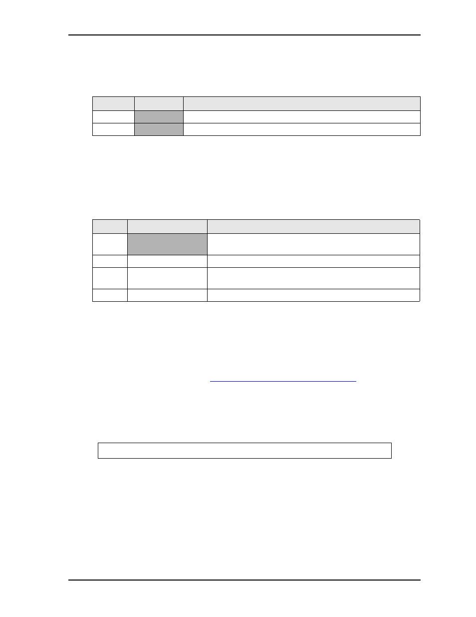
Battery
lists the pin signals of the External Battery Input header for backup RTC (Real Time Clock),
which uses 2 pins with 0.049" (1.25mm) pitch.
Note: The shaded table cells denote power or ground. The RTC pin has an expected current draw of
~36
A at room temperature. The battery is used only when power is not applied to the board.
Ethernet External LED
This header provides signals for an external LED that indicates Ethernet links and activity using a single row
of 4 pins with 0.049" (1.25mm) pitch.
Note: The shaded table cell denotes power.
Miscellaneous
SSD (Solid State Drive)
The CoreModule 720 provides an 8GB SATA SSD, which is soldered directly onto the board. For more
information refer to the SSD data sheet:
http://www.greenliant.com/dotAsset/45628.pdf
.
Real Time Clock (RTC)
The CoreModule 720 contains a Real Time Clock (RTC). The RTC can be backed up with a battery. If the
battery is not present, a battery-free boot function in the BIOS completes the boot process and resets the
clock to the default date and time.
Table 3-20. External Battery Input Header (J20)
Pin #
Signal
Description
1
VBAT_EXT
+3.0 volts DC
2
GND Ground
Table 3-21. Ethernet External LED Pin Signals (J9)
Pin #
Signal
Description
1
V3.3_CONN
+3 volts – Provides +3 volts to external LED (Pins 1-2 for Green
LED)
2
ETH_ACT_LED
Ethernet Activity
3
ETH_LINK100_LED
Fast Ethernet Link with +3 volts power (Pins 3-4 for Bi-Color
LED)
4
ETH_LINK1000_LED Gigabit Ethernet Link
NOTE
Some operating systems require a valid default date and time to function.