5 dp connector, 1 display mode selection, 2 power output modification for hdmi – ADLINK ETX-BT User Manual
Page 32: Display mode selection, Power output modification for hdmi
Page 32
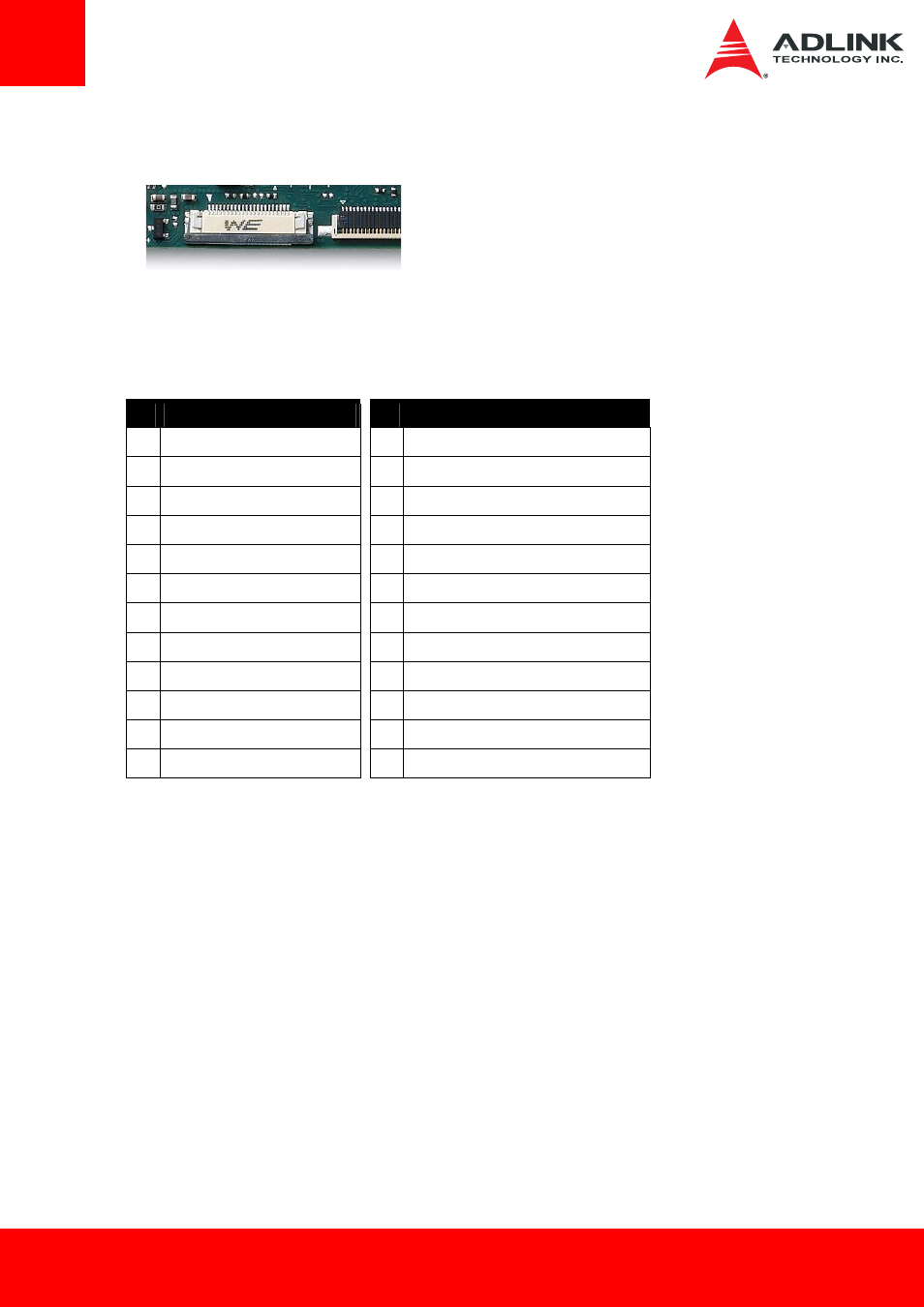
6.5 DP Connector
Connector Type: Wurth WE 6871 2214 522
The DP connector brings out DDI1 port of the Intel® Atom™ SoC as either DP or HDMI/DVI on a
flat cable connector.
Pin
Definitions
Pin Signal Description (DP / HDMI)
Pin Signal Description (DP / HDMI)
1
GND
11 DP_LANE3+ / TMDS1_CLK+
2
DP_LANE0+ / TMDS_DATA2+ 12 DP_LANE3- / TMDS1_CLK-
3
DP_LANE0- / TMDS_DATA2-
13 CONFIG1
4
GND
14 CONFIG2 (not used)
5
DP_LANE1+ / TMDS_DATA1+ 15 GND
6
DP_LANE1- / TMDS_DATA1-
16 DP_AUX+ / HMDI1_CTRLCLK (3.3V !)
7
GND
17 DP_AUX- / HMDI1_CTRDATA (3.3V !)
8
DP_LANE2+ / TMDS_DATA0+ 18 GND
9
DP_LANE2- / TMDS_DATA0-
19 DP_HPD# / HDMI_HPD# !!
10 GND
20 + DP_PWR only (3.3V)
11 DP_LANE3+ / TMDS1_CLK+
21 + DP_PWR only (3.3V)
12 DP_LANE3- / TMDS1_CLK-
22 + DP_PWR only (3.3V)
6.5.1
Display Mode Selection
Display mode (DP or HDMI/DVI) can be selected by strapping pin 13 (CONFIG1).
Strapping should be done on the carrier as follows
- Pull high to 3.3V (3VS0) for HDMI/DVI
- Pull to GND for DisplayPort mode
6.5.2
Power Output Modification for HDMI
For HDMI/DVI output, pins 16, 17, should be converted to 5V (5VS0) on the carrier by level
shifters
1 22