4 xdp debug header, Page 31 – ADLINK ETX-BT User Manual
Page 31
Page 31
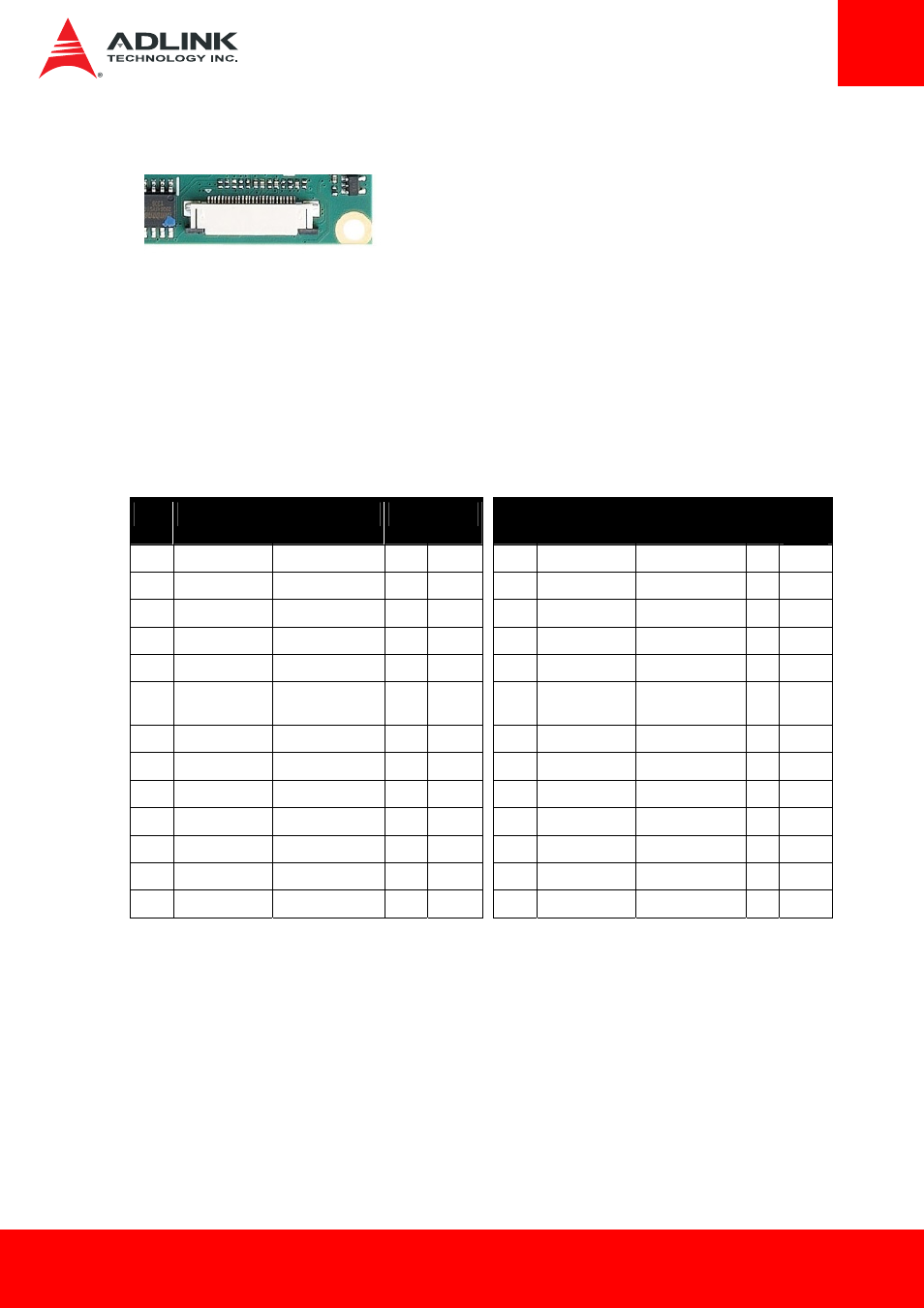
6.4 XDP Debug Header
Connector Type: Molex 26-pin 52435-2671
The debug port is a connection into a target-system environment that provides access to JTAG,
run control, system control, and observation resources. The XDP target system connector is a
Molex 26-pin 52435-2671 connector. Specific plating types, locking clips, and alignment pin
details of this connector can be obtained from Molex. No specific plating types, locking clips or
alignment pins are required for the XDP tool.
Pin Definitions (on ETX module)
Pin
XDP Signal
Target Signal
I/O
Device
Pin
XDP Signal
Target Signal
I/O Devic
e
1 OBSFN_A0 TAP_PREQ# I/O
SoC 2 OBSFN_A1 TAP_PRDY# I/O
SoC
3 GND
GND
NA
4 OBSDATA_A[0]
DBG[0]
I/O
SoC
5 OBSDATA_A[1]
DBG[1]
I/O
SoC 6 GND
GND
NA
7
OBSDATA_A[2] DBG[2]
I/O SoC
8
OBSDATA_A[3] DBG[3]
I/O SoC
9 GND
GND
NA
10 HOOK0
PMC_RSMRST#
I SoC
11
HOOK1 PMIC_PWRBTN#
O
System
12
HOOK2 PMC_CORE_PW
ROK
I SoC
13
HOOK3 ILB_RTC_TEST#
O
SoC
14
HOOK4 Open
NA
15 HOOK5
Open
NA
16 VCCOBS_AB 1.8VS
(SUS) I System
17
HOOK6 PMC_PLTRST#
I
SoC
18
HOOK7 PMC_RSTBTN#
O
SoC
19 GND
GND
NA
20 TDO
TAP_TDO
I SoC
21 TRSTn
TAP_TRST#
O SoC 22 TDI
TAP_TDI
O SoC
23 TMS
TAP_TMS
O SoC 24 TCK1
Open
NA
25 GND
GND
NA
26 TCK0
TAP_TCK
O SoC
Refer to the "Bay Trail M/D/I Platform” Debug Port Design Guide (DPDG),
Document Number: 512816, Revision: 2.1
Testing on the XDP connector was carried out with Intel® System Studio 2014 – JTAG Debugger
ITP-XDP3
1
26