ADLINK ASD8P-MT1 Series User Manual
Page 14
Page 14 of 43
ASD8P-MT1 Specification
Reliability
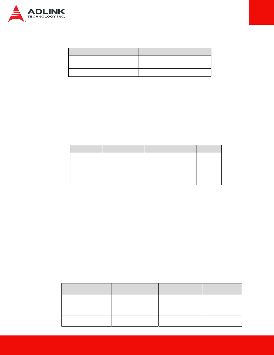
Table 10. Reliability specifications
Parameter
Value
Mean Time between Failure
(MTBF)
> 1,500,000 hours
Power on/off cycles
50000 cycles
Notes:
1) MTBF is calculated based on a Part Stress Analysis. It assumes nominal voltage.
With all other parameters within specified range.
2) Power on/off cycles is defined as power being removed from the drive, and the
restored. Most host systems remove power from the drive when entering suspend and
hibernate as well as on a system shutdown.
Shock and Vibration
Table 11. Shock and Vibration
Item
Mode
Timing/Frequency
Max
Non-operating
At 1 msec half-sine
1500G
Shock
1
Non-operating
At 2 msec half-sine
1000G
Operation
7~800 Hz
3. 08 Grms
Vibration
2
Non-operation
20~2000 Hz
16. 3 Grms
Notes:
1) Shock specifications assume that the SSD is mounted securely with the input
vibration applied to the drive mounting screws. Stimulus may be applied in the X, Y or
Z axis.
2) Vibration specifications assume that the SSD is mounted securely with the input
vibration applied to the drive mounting screws. Stimulus may be applied in the X, Y or
Z axis. The measured specification is in root mean squared form.
Electromagnetic Immunity
Electromagnetic Immunity tests assume the SSD is properly installed in the representative host
system. The drive operates properly without errors degradation in performance when subjected to
radio frequency (RF) environments defined in the following table.
Table 12. Radio Frequency Specifications
Test
Description
Performance
criteria
Reference
standard
Electrostatic discharge
Contact ±4KV
Air: ±8KV
A
IEC 61000-4-2:
2008
Electrostatic discharge
Contact ±6KV
Air: ±12KV
B
IEC 61000-4-2:
2008
Electrostatic discharge
Contact ±8KV
Air: ±15KV
C
IEC 61000-4-2:
2008