Cpld – ADLINK aTCA-N700 User Manual
Page 46
aTCA-RN720 User's Guide
46
The LED indication is mapped to the LED data values as shown in Table 8-1.
Table 8-1 LED Data and E and L/A LED Indication per Port
LINK-EN
LINK
ACT
Description
E
status
L/A
status
1 1
1
Link-en/Act
ON BLINK
1 1
0
Link-en/Link
ON ON
1 0
0
Link-en/No
Link
ON OFF
0
0
0
Link Disable /No Link
OFF
OFF
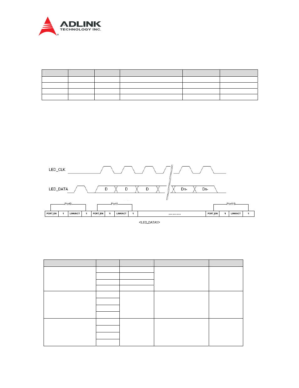
The LED DATA from the Zone 3 connector to the RTM is RTM_LED_DATA1. The aTCA-N700
front blade sends the stream as in Figure 8-2 where the ports are arranged as in
Table 8-2. The RTM CPLD picks up necessary port information and distributes to the
corresponding QSFP/SFPs. The preamble is a LED_DATA HIGH pulse without a clock. The
CPLD deserializes the LED data and drives corresponding SFP port LEDs accordingly. The
switch serdes numbers are per aTCA-N700 front blade.
(a) aTCA-N700 front blade
Figure 8-2 Zone 3 RTM_LED_DATA format
Table 8-2 LED_DATA1 Stream: aTCA-N700 front blade
Data Port No.
DataBit
Description
Switch Serdes No.
Port Name.
0 PORT_EN
1 1
2 LINK/ACT
Port 0
3 1
57 R-P01
4
5
6
Port 1
7
Don't care
Don't care
X
8
9
10
Port 2
11
Don't care
Don't care
X