4 installation and operation, 1 hardware configuration setting, 1 headers/jumpers – ADLINK aTCA-N700 User Manual
Page 13: Table 3-3 zone 3 connector pin-out: p2
aTCA-RN720 User's Guide
13
4 Installation and Operation
Before installing the aTCA-RN720, make sure that the following are ready or checked to insure
proper installation and operation:
z
An ATCA chassis with a reserved slot for the front blade and the aTCA-RN720. Note that
any front blade with identical Zone 3 pin assignment can use the aTCA-RN720.
z
A console PC that runs a serial port monitoring or terminal emulation program
z
Software: All the necessary firmware are programmed into the EEPROM/flash memories
upon delivery of the board
z
The aTCA-RN720 Users Guide, this document
4.1 Hardware Configuration Setting
For usual operation, users are not recommended to change any on-board hardware configuration
setting, but there are some options on the board for those want to investigate more flexibility for
testing.
4.1.1 Headers/Jumpers
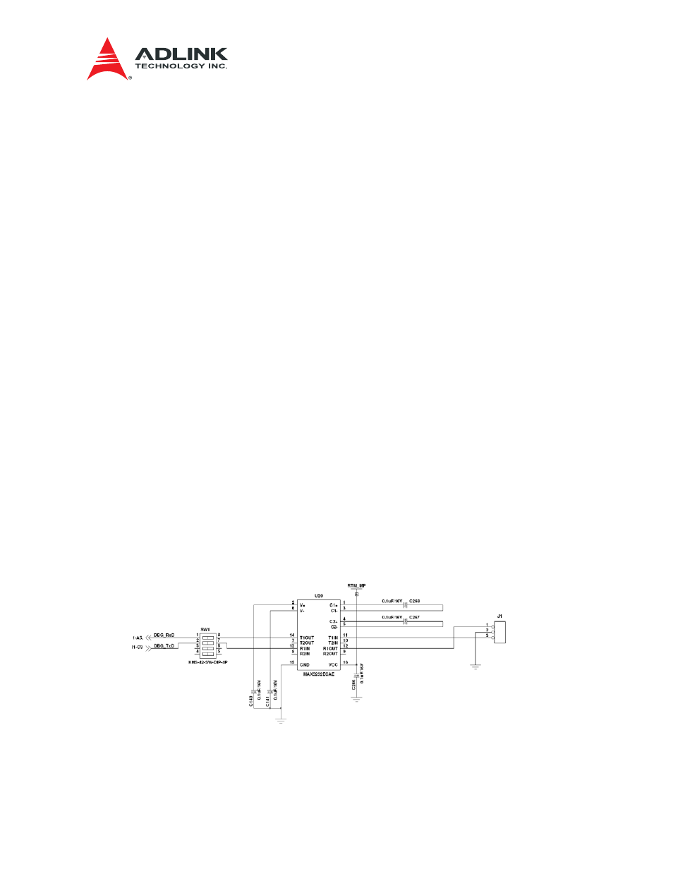
The J1 Header is used for debugging using a local UART. When a front blade monitoring is not
available, an extra console may be connected through this header. Refer to Figure 4-1 for
connections.
The J15 is provided for In System Programming (ISP) for the MMC as shown in Figure 4-2.
Figure 4-1 Header J1 and Switch SW1