4 zone 3 interface, External interfaces, 1 front – ADLINK aTCA-N700 User Manual
Page 11: Panel overview, 2 traffic, Service port, 3 leds, Markers
aTCA-RN720 User's Guide
11
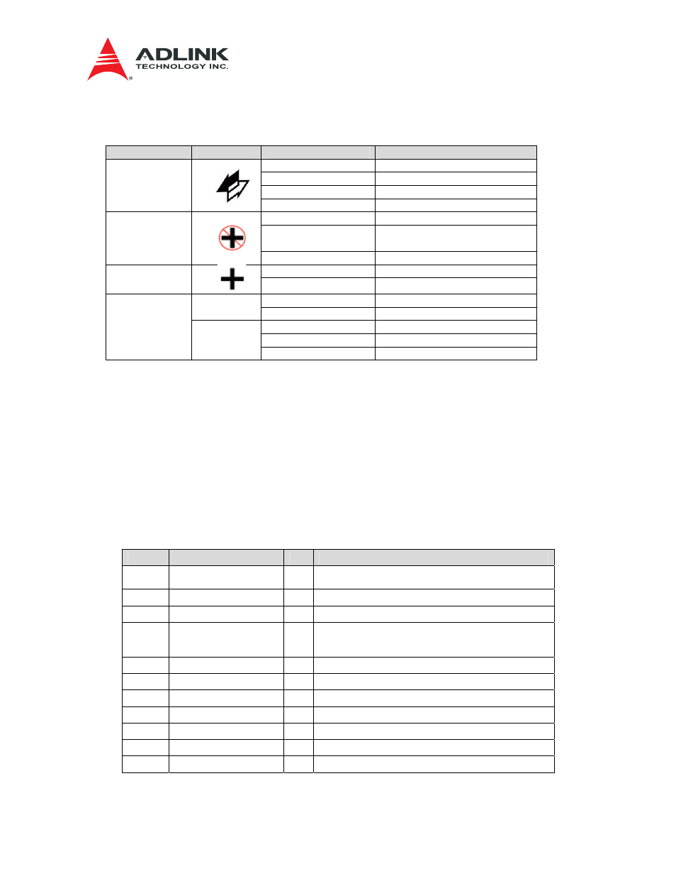
Table 3-1 Faceplate LEDs and Markers
Name
Marker
Display
Description
Blue Solid
DC-DC Power OFF(M1)
Blue Short Blink
Hot swap Operation(M5/M6)
Blue Long Blink
Hot swap Operation(M2)
HS LED
OFF Normal
Operation(M3/M4)
Red Solid
Out of Service(M1)
Red Blink
Out of Service or Service
Preparation (M5/M6)
OOS LED
OFF
Normal Operation (M3/M4)
Green Solid
Power GOOD
Power GOOD
LED
OFF Power
Fail
Green Solid
Enabled
E
OFF Not
Enabled
Green On
Link Up
Green Blink
Link Activity
Service Port
L/A
OFF Link
Down
3.4 Zone 3 Interface
The two Zone 3 connectors are used for the front blade connection. For the data plane interface,
Twelve Serdes lanes are routed to the Zone 3 connectors. The twelve pairs of 10G Serdes lanes
are connected to the front blade. The Serdes lanes are configured for 2 x XLAUI, and 4x SFI
interfaces. Table 3-2 and Table 3-3show the detailed signal definitions.
Table 3-2 Zone 3 Connector Pin-out: P1
Note*I/O is from the viewpoint of the Front Blade. Unspecified pins are N.C.
Pin No
Signal Name
I/O*
Description
A1~C1,
A2~C2
RTM_12V
O
RTM 12V from Front Blade
D1
RTM_MP
O
RTM 3.3V from Front Blade
F1
RTM_INSERT
I
RTM Presence signal to IPMC (to GPIO)
H1 RTM_ENABLE
O
RTM Enable signal driven by IPMC (via
GPIO). Implements ENABLE# per AMC.0 Section
3.6.
E2
RTM_SCL
O
IPMB-L from IPMC to RTM MMC
F2
RTM_SDA
O
IPMB-L from IPMC to RTM MMC
C4
IRQ_RTM
I
Interrupt to LMP
H4
RTM_RESET
O
Reset signal from LMP to RTM
A5
DIAG_EN
O
DIAG_TEST Enable
G6
LMP_RTM_SCL
O
LMP I2C for RTM
H6
LMP_RTM_SDA
I/O
LMP I2C for RTM