Table 7-8 signals: rtm shutdown procedure, Table 7-9 signals: hot swap procedure – ADLINK aTCA-N700 User Manual
Page 43
aTCA-RN720 User's Guide
43
RTM Hot Swap
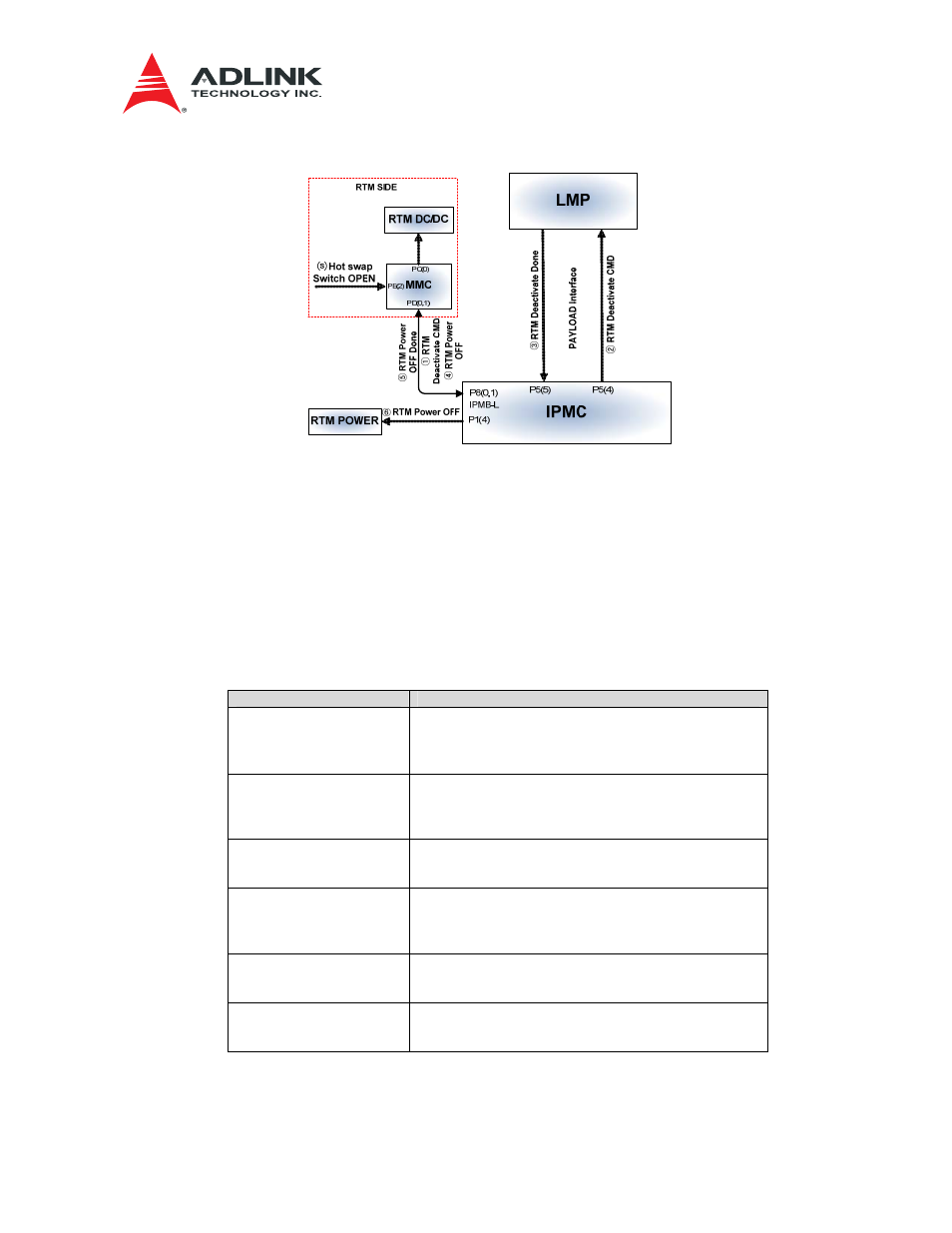
Figure 7-10 RTM Hot Swap Procedure
⒮
RTM Hot swap switch open operation triggers a signal to MMC.
①
MMC sends RTM Deactivate command to IPMC.
②
IPMC forwards RTM Deactivate command to LMP via PAYLOAD Interface (UART).
③
LMP completes the operation and sends the completion message to IPMC via PAYLOAD
Interface (UART).
④
IPMC sends RTM Power OFF to MMC via IPMB-L.
⑤
MMC completes operation and sends the completion message to IPMC.
⑥
IPMC turns off RTM Power 12V.
Table 7-10 Signals: RTM Hot Swap Procedure
Signal name
Status
PAYLOAD Interface
IPMC : P5(4),P5(5)
RTM Deactivate Command
- IPMI Message
RTM Deactivate Done Indicator
- IPMI Message
IPMB-L
IPMC : P8(0),P8(1)
RTM Power OFF
- IPMI Message
RTM Power OFF Done
- IPMI Message
IPMC : P1(4)
RTM Power 12V OFF
0 : Power OFF
1 : Power ON
IPMB-L
MMC : PD(0),PD(1)
RTM Power OFF
- IPMI Message
RTM Power OFF Done
- IPMI Message
MMC : PC(0)
RTM Internal Power OFF
0 : Power ON
1 : Power OFF
MMC : PE(2)
Hot swap Indicator
0 : Hot swap Indicator
1 : Normal operation