2 12v or large page 5v flash disk – Acrosser AR-B1047 User Manual
Page 21
AR-B1047 User’s Guide
3-6
Step 8: Install EPROM chips
Be sure to place the programmed EPROMs (R01, R02…) into socket starting from MEM1 and ensure that
the chips are installed in the sockets in the proper orientation.
3.2.2 12V or Large Page 5V FLASH Disk
If you are using 12V FLASH or large page 5V FLASH as ROM disk, you have to followed the same procedure as
step 1 to step 4 by using the UV EPROM.
CAUTION: If you want to use the 12V FLASH, please use the external 12V voltage, the AR-B1047 does not
support the 12V voltage.
(1) Switch and Jumper Setting
Step 1: Use jumper block to set the memory type as ROM (FLASH).
Step 2: Use jumper JP1 to select the correct EPROM/FLASH type.
Step 3: Select the proper I/O base port, firmware address, disk drive number and EPROM/FLASH type on SW1.
Step 4: Insert programmed EPROM(s) or FLASH(s) chips into sockets starting at MEM1.
Step 5: Line up and insert the AR-B1047 card into any free slot of your computer.
Step 6: If 12V FLASH or large page 5V FLASH is being installed for the first time, use the FLASH programming
utility PGM1047.EXE to program ROM pattern files, which have been generated by RFG.EXE, onto the
FLASH chips.
ON
1
2
3
4
5
6
7
8
OFF
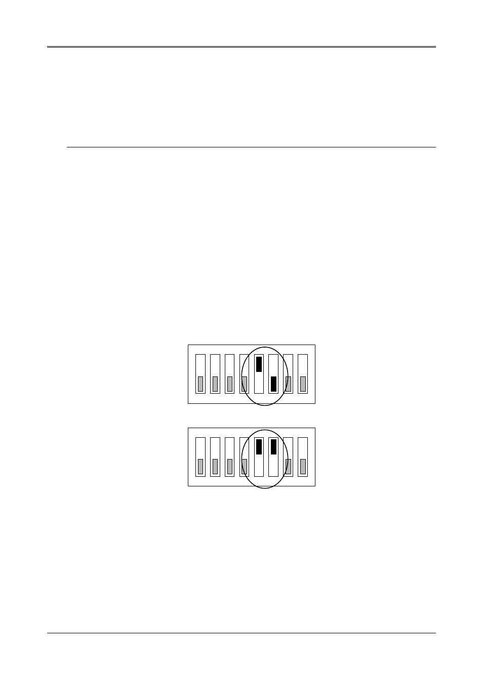
Figure 3-3 5V Large FLASH (29FXXX) Switch Setting
ON
1
2
3
4
5
6
7
8
OFF
Figure 3-4 12V FLASH (28FXXX) Switch Setting