Adcom GTP-740 User Manual
Page 15
Attention! The text in this document has been recognized automatically. To view the original document, you can use the "Original mode".
VCR inputs and outputs;
(see illustration on preceding page)
Because you will use your VCR to record as well as play, take care to follow these
instructions carefully.
1) Connect the VCR’s composite video output to the GTP-740's
yellow-center
RCA
jack
immediately under the “VCR in" label.
2) Connect the VCR’s composite video input to the GTP-740's yellow-center RCA jack
immediately under the “VCR out” label.
3) Connect the VCR’s left channel analog audio output to the GTP-740's white “VCR in"
jack.
4) Connect the VCR’s right channel analog audio output to the red “VCR in" jack.
5) Connect the VCR’s left channel analog audio input to the GTP-740’s white "VCR out”
jack.
6) Connect the VCR’s right channel analog audio input to the red “VCR out” jack.
Note: You may want to use so-called “AA/ combination" patch cords to make this step
less confusing. Sold under a variety of names, these combination cables usually include
a video conductor and two audio conductors in one cable assembly. If you elect to use
them, make sure that they support the video format (composite or S-Video) you’ve
chosen for your system.
Video aux input:
(see illustration on preceding page)
This input is electrically identical to the LD input described above and will accommodate a
wide variety of audio/video sources.
After selecting and connecting the source’s composite or S-Video output to the GTP-740’s
corresponding “video aux" video input, connect the source’s left channel analog audio
output to the white RCA jack under the “video aux in" label. Then connect the
SQurce’s
right channel analog audio output to the red RCA jack under the “video aux in" label.
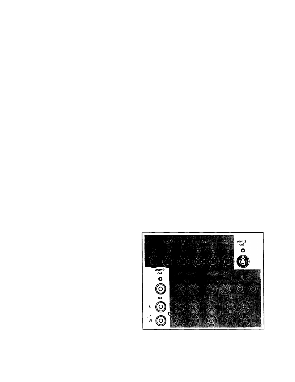
Room 2 outputs:
These outputs supply video
and audio signals for
distribution to a secondary
area or room in your home.
Room 2 features are
covered in a separate
section of this manual.
Connect the composite
Room 2 video output to the
video display device (TV or
video projector) in the
remote area. Make sure the
cable(s) you use for this
connection are high quality
and well shielded as long
cable runs act as antennas
for unwanted interference signals. (Depending on the distance between the GTP-740 and
the display device and, to a lesser extent, the video format you’ve chosen, you may need
14