Installation, 1) le/mfh-u surface-mounting to mbw-a back box, 2) lef/mfh-u surface-mounting (on gang boxes) – Aiphone MFH-U User Manual
Page 3: 3) lef-b/mfh-ub semi-flush mounting to wall
Attention! The text in this document has been recognized automatically. To view the original document, you can use the "Original mode".
INSTALLATION
(1) lE/MFH-U surface-mounting to MBW-A back box;
lE-lGD(U)
IE-2AD(U)
Line A
Cut a hole 95 mm (3-3/4") high by 215 mm
(8-1/2") wide and 40 mm (1-9/16") deep into
the wall. Position the MBW-A box in the
wall, with the V-cut in the upper position, so
v-cut that line A crosses vertically with the floor.
MBW-A
To mount the MFH-U, remove the top screw in the case, and separate front case from the chassis, pushing the bottom, right
of front case upward, then the left side of the case to the right, and removing the connector. Attach the chassis to MBW-A
and reattach the front case. To mount IE intercom, attach mounting bracket to MBW-A and mount the unit onto the bracket.
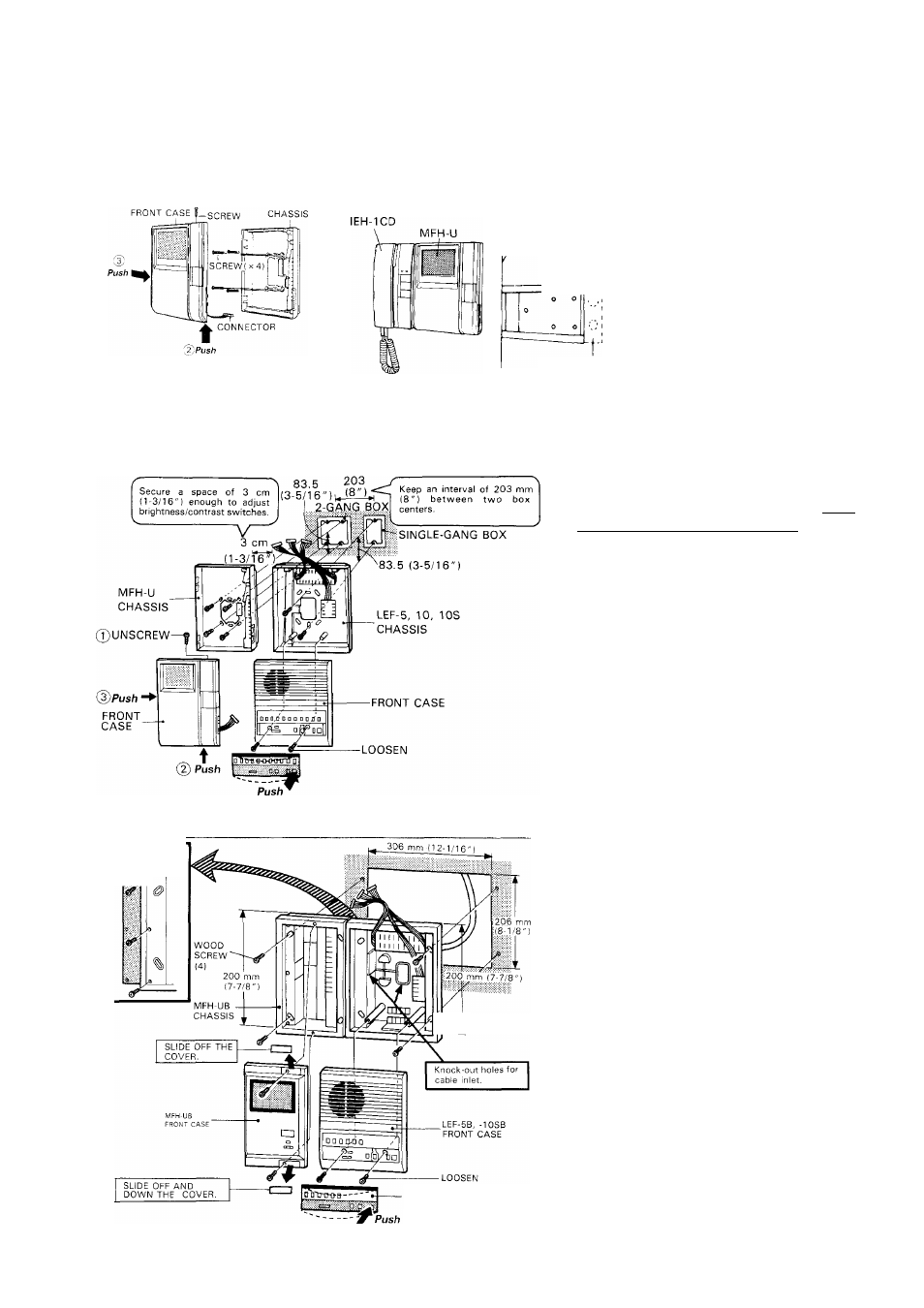
(2) LEF/MFH-U surface-mounting (on gang boxes);
When mounting LEE master & MFH-U video
monitor side by side, be sure to locate
MFH-U to the left of LEF master, keeping
a space of 3 to 5 cm (1-3/16" to 2") for
brightness and contrast adjustment.
First, separate each chassis from front case.
Mount the chassis with the supplied screws.
After wiring, reattach connectors and front
case to chassis.
(3) LEF-B/MFH-UB semi-flush mounting to wall;
JUNCTION
LEF-B
HARDWARE
CHAVIS
-LEF-5B, -10SB
CHASSIS
To mount LEF-5B/10SB and MFH-UB units,
cut and open a hole of H: 206 x W: 306 (mm)
(H: 8-1/8" X W: 12-1/16"), keeping a space
of 3 to 5 cm (1-3/16" to 2") on each side.
Before installation, join together both LEF-
B and MFH-UB chassis by attaching a
junction hardware with 3 screws (supplied).
Attach two chassises with 4 wood screws
(supplied).
After wiring, remount front cases to each
chassis.
BUTTON-IDENTIFICATION
PLATE.