Cutting deck engagement adjustment, Wheel adjustment – Bolens TMO-3394704 User Manual
Page 13
Attention! The text in this document has been recognized automatically. To view the original document, you can use the "Original mode".
CUTTING DECK ENGAGEMENT ADJUSTMENT
The cutting deck engagement may be adjusted to
make certain deck is disengaged when lift and disen
gagement lever is in the disengaged position, or to
obtain more drive in the cutting positions. Correct
adjustment as follows.
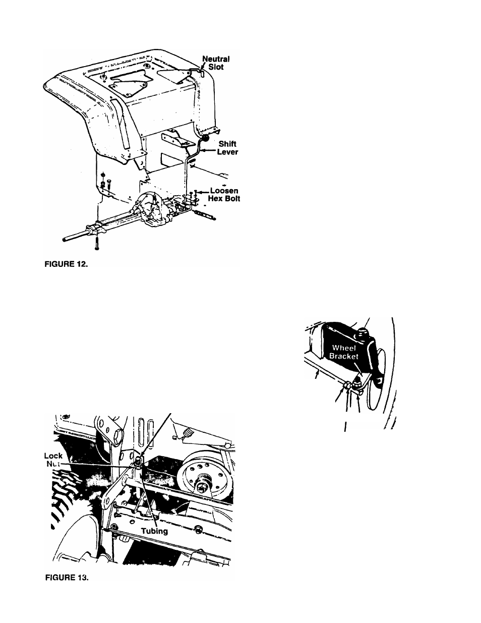
Place the lift and disengagement lever in the highest
cutting position (first notch down from disengaged
position). The approximate adjustment is to have the
lock nut on the threaded rod (above the rear of the
deck) touching the end of the tubing. See figure 13.
Threaded
Rod
Move the lock nut toward the tubing to start to disen
gage the deck earlier. Move the lock nut away from
the tubing to obtain more drive in the cutting positions.
A
WARNING:
Make
certain
the
unit
is
ad]usted so that the cutting blades are
disengaged when the lift and disengage
ment iever is in the disengaged position.
WHEEL ADJUSTMENT
The caster (forward slant of the king pin) and the
camber (tilt of the wheels out at the top) require no
adjustment. Automotive steering principles have been
used to determine the caster and camber on the trac
tor. The front wheels should toe-in 1/8 inch.
To adjust the toe-in, follow these steps.
1. Remove the hex nut and lock washer, and drop
the tie rod end from the wheel bracket. See figure
14.
2. Loosen the hex jam nut on tie rod.
3. Adjust the tie rod assembly for correct toe-in.
(See figure 14.) Retighten hex jam nut.
Tie
Rod
Hex
Nut
:Jam
Tie Rod'
End
Hex Nut
Lock Washer
FIGURE 14.
Dimension "B” should be approximately 1/8" less than
Dimension “A.” See figure 15.
A. ) To increase Dimension “B,” thread the rod into
tie rod end.
B. ) To decrease Dimension "B,” unscrew the tie rod
from the tie rod end.
C. ) Reassemble tie rod. Check dimensions. Readjust
if necessary.
13