Section 6 — allowing for clearances – Bard Bayrd Furnace 403293A User Manual
Page 9
Attention! The text in this document has been recognized automatically. To view the original document, you can use the "Original mode".
9.
Rgmove four screws that secure bottom plate to cas
ing sides. Remove bottom plate; save screws,
10.
Install top plate, removed in step 2, where bottom
plate was. Secure with four screws. Inducer outlet is
now lined up with vent outlet in top plate.
11.
Stand up furnace with top plate down. Line front duct
flange up with holes. Place bottom plate on top of
duct flange and secure both to casing with four
screws.
12.
Install junction box on bottom plate using two #6B
screws removed in Step 2. Junction box cover and
screw of junction box must face front of furnace.
13.
Gasket around flue collar must be in place. If gasket
is loose, glue It. If gasket is damaged, replace it.
14.
Install a single wall vent pipe section (minimum length
30 inches) (Field-Supplied) to inducer outlet with three
equally spaced screws. This pipe serves as an in
ducer outlet extension to which an appropriate vent
can be attached. Due to minor variations in vent pipe,
available from different manufacturers in the field,
and to assure the tightest seal possible, inducer out
let extension is not supplied with furnace. Additional
vent pipe sections or Type B1 adapter may then be
added when installing the furnace.
WARNINGS If Inducer outlet extension Is shorter than
30 Inches and chimney or vent becomes blocked, com
bustion products may be drawn Into furnace. This could
cause nausea or asphyxiation, resulting In Injury or death.
15.
Conversion from as-shipped configuration is now
complete.
SECTION 6 — ALLOWING FOR CLEARANCES.
WARNING: Do not Install furnace on Its back, doing so
could cause a fire, resulting In damage. Injury or death.
Establishing clearances from combustible material.
Locate clearance label on inside of front door. See Figure 6.
WARNINGS Furnace Installation must meet all minimum
clearances from combustible material specified In this
manual and all applicable codes. Failure to provide re
quired clearance between furnace and combustible mate
rials could cause a fire, resulting In damage, injury, or
death.
WARNINGS This furnace Is A.G.A. design certified for
direct Installation on wood flooring for upflow and hori
zontal positions.
• Do not install furnace on carpeting, tile or other
combustible material.
• Do not Install furnace In a closet In horizontal
position.
• Do not Install furnace on wood flooring without
special base In downflow position.
Doing any of the above could cause a fire resulting in
damage, injury, or death.
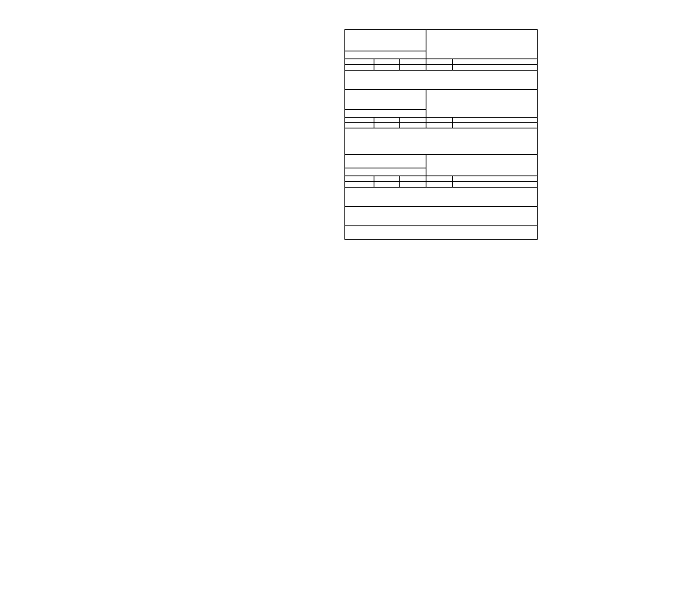
MINIMUM INCHES CLEARANCE
CLOSET.
UPFLOW POSITION
0 COMBUSTIBLE MATERIAL IN ALCOVE OR
FRONT VENT
TOP SIDES BACK
1
1*
0
6
6 WHEN USING SINGLE WALL
1
0
0
2
1 WHEN USING B1
• FOR CASING WIDTHS 17 INCHES OR LARGER 0 CLEARANCE MAY
BE USED. 18 INCH FRONT CLEARANCE REQUIRED FOR ALCOVE. FOR
INSTALLATION ON COMBUSTIBLE FLOORING.
MINIMUM INCHES CLEARANCE
CLOSET.
DOWNFLOW POSITJON
0 COMBUSTIBLE MATERIAL IN ALCOVE OR
FRONT VENT
TOP SIDES BACK
1
1*
0
6
6 WHEN USING SINGLE WALL
1
0
0
2
1 WHEN USING B1
• FOR CASING WIDTHS 17 INCHES OR LARGER 0 CLEARANCE MAY
BE USED. 18 INCH FRONT CLEARANCE REOUIRED FOR ALCOVE. FOR
INSTALLATION ON COMBUSTIBLE FLOORING ONLY WHEN INSTALLED ON
SPECIAL BASE PART N0. 4-024400.
MINIMUM INCHES CLEARANCE
HORiZONTAL POSmON
rO COMBUSTIBLE MATERIAL IN ALCOVE.
FRONT VENT
TOP SIDES* BACK
1
2*
0
18
6 WHEN USING SINGLE WALL
1
2*
0
18
1 WHEN USING B1
• CLEARANCE SHOWN IS FOR AIR INLET AND AIR OUTLET ENDS.
VENT MUST MAINTAIN CLEARANCE LISTED ABOVE.
FOR INSTALLATION ON COMBUSTIBLE FLOORING.
FOR HORIZONTAL POSITION LINE CONTACT IS ONLY PERMISSIBLE
BETWEEN LINES FORMED BY INTERSECTIONS OF TOP AND TWO SIDES OF
FURNACE JACKET AND BUILDING JOISTS. STUDS OR FRAMING.
ALL POSITIONS RLOUIRE 30 INCHES FRONT CLEARANCE FOR SERVICE*
40ZB№
MINIMUM CLEARANCES
FROM COMBUSTIBLE MATERIALS
FIGURE 6
1. Upflow Installation.
Upflow position is approved for installation on
wood flooring. Typical upflow furnace installa
tions are an alcove, attic, basement, closet, ga
rage, or utility room. See Figure 6 or furnace
clearance plate for minimum clearances to com
bustible materials.
2.
Horizontal Installation
a.
Horizontal position is approved for installa
tion on wood flooring. Typical horizontal fur
nace installations are an alcove, garage, at
tic, or crawl space. See Figure 6 or furnace
clearance plate for minimum clearances to
combustible materials.
b.
Attic Installation.
Line contact is permissible for furnaces
installed in horizontal positions. The in
tersection of furnace top and sides forms
a line. This line may be in contact with
combustible
material.
However,
maintain
a 6" clearance to vent connection unless
Type B1 vent is used. See Figure 7.