Bard Bayrd Furnace 403293A User Manual
Page 42
Attention! The text in this document has been recognized automatically. To view the original document, you can use the "Original mode".
b. The minimum capacity (Fan Min.) shaH be
determined
by
referring
to
the
corresponding single appliance table
(Tables 1 and 2). In this case, for each
appliance the entire vent connector and
common vent from the appliance to the
vent termination would be treated as a
single appliance vent, as if the other
appliances were not present.
5)
If vent connectors are combined prior to
entering the common vent, the maximum
common vent capacity listed in the common
venting tables must be reduced by 10%. the
equivalent of 1 (one) 90® elbow (0.90 x
maximum common vent capacity). See Figure
11
The horizontal length of the common vent
connect or manifold (L) should not exceed
1-1/2 feet (18 inches) for each inch of
common vent connector manifold diameter.
6)
If the common vertical vent is offset as shown
in Figure 8. the maximum common vent
capacity listed in the common venting tables
should be reduced by 20%, the equivalent of
2 (two) 90® elbows (0.80 x maximum common
vent capacity). The horizontal length of the
offset shall not exceed 1 1/2 feet for each
inch of common vent diameter.
7) The common vent diameter must always be at
least as large as the largest vent connector
diameter. All interconnection fittings must
also be the same size as the common vent.
8)
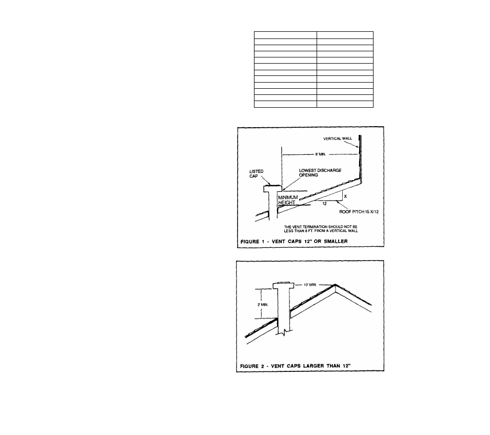
Type 6 gas vents shall terminate above the
roof surface with a listed cap or a listed roof
assembly in accordance with the terms of their
respective
listings
and
the
vent
manufacturer's instructions.
VENT CAPS 12" AND SMALLER
Listed gas venting systems using listed vent
caps 12" and smaller in size may terminate in
accordance with the VENT TERMINATION
TABLE. (SEE FIGURE 1)
VENT CAPS LARGER THAN 12"
Listed ve/it caps
larger
than 12" must be
located at least 2 feet above the highest point
and at least 2 feet higher than any portion of a
building within a horizontal distance of 10
Feet. (SEE FIGURE 2)
9)
Use sea level input rating when determining
maximum capacity for high attitude installation.
Use actual input rating for determining
minimum capacity for high attitude installation.
GAS VENT TERMINATION TABLE
ROOF PITCH
MINIMUM HEIGHT
FLAT TO 7/12
1.0 FEET *
OVER 7/12 TO 8/12
1.5 FEET
OVER 8/12 TO 9/12
2.0 FEET
OVER 9/12 TO 10/12
2.5 FEET
OVER 10/12 TO 11/12
3.25 FEET
OVER 11/12 TO 12/12
4.0 FEET
OVER 12/12 TO 14/12
5.0 FEET
OVER 14/12 TO 16/12
6.0 FEET
OVER 16/12 TO 18/12
7.0 FEET
OVER 18/12 TO 20/12
7.5 FEET
OVER 20/12 TO 21/12
8.0 FEET
* THIS REQUIREMENT COVERS MOST INSTALLATIONS
40