Bard Bayrd Furnace 403293A User Manual
Page 44
Attention! The text in this document has been recognized automatically. To view the original document, you can use the "Original mode".
22)
Listed, corrugated metallic chimney liner
systems in masonry chimneys shall be sized
by using Tables 1 or 2 tor dedicated venting
and Tables 3 or 4 for common venting with
the maximum capacity reduced by 0.20%
(0.80
X
maximum capacity) and the minimum
capacity as shown in the applicable table.
Corrugated metal vent systems installed with
bends or offsets require additional reduction
of the vent maximum capacity (See Note 6).
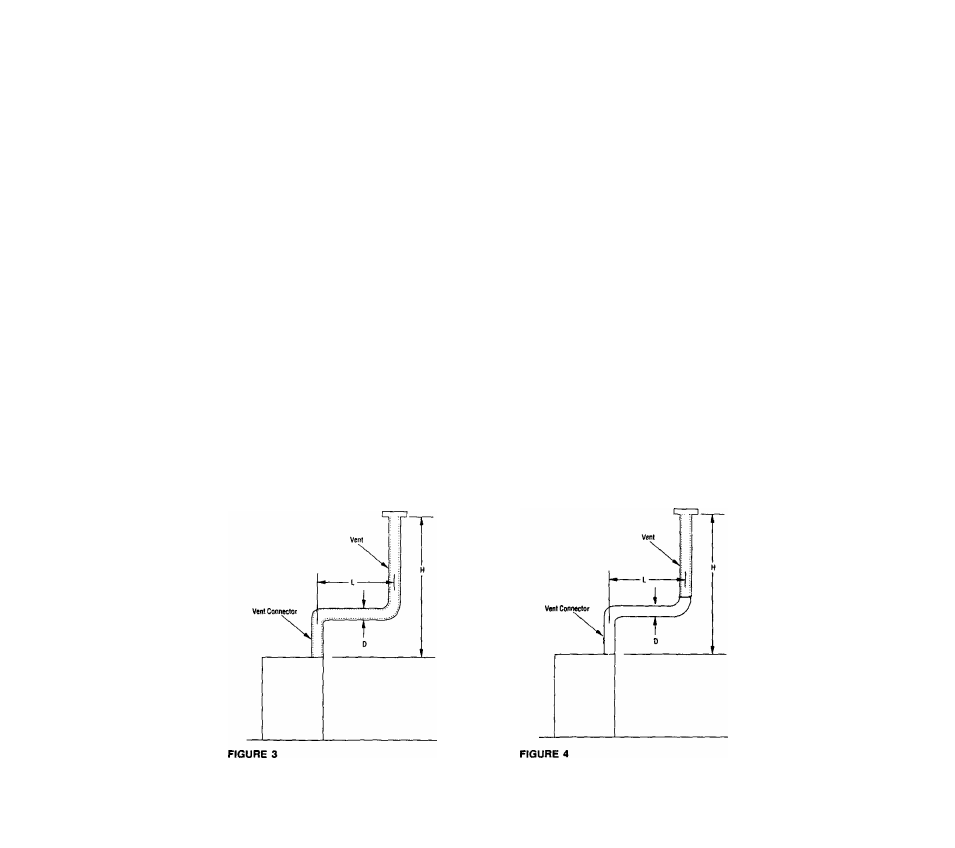
23) For multiple units of gas utilization equipment
all located on one floor, available total height
"H" is measured from the highest drafthood
outlet or flue collar up to the level of the cap or
terminal. Connector rise "R" is measured from
the drafthood outlet or flue collar to the level
where the vent gas streams come together.
(Not applicable to multi-story).
24)
For multi-story installations, available total
height for each segment of the system *'H" is
the vertical distance between the highest
drafthood outlet or flue collar entering that
segment and the centerline of the next
higher interconnection tee (See Figure 13).
25) The size of the lowest connector and of the
vertical
vent
leading
to
the
lowest
interconnection of a multi-story system must
be in accordance with Table 1 OR 2, for
available total height "H" up to the lowest
interconnection (See Figure 14).
26) Common vents in multi-story systems shall be
type B when used in multi-story systems and
have no offsets.
27) Numbers followed by an asterisk (*) in Table 6,
indicate
the
possibility of continuous
condensation, depending on locality. Consult
appliance manufacturer, local serving gas
supplier, and/or authority having jurisdiction.
28) In a single run of vent or vent connector, more
than one diameter and type of pipe are
permitted to be used, provided that all the size
are permitted by the tables.
29) If the desired vent height and connector rise
and/or lateral are between the table entries,
linear interpolation is permitted for calculation
of the permissible appliance input ratrings.
Extrapolation beyond the table entries is not
recommended. (See Example 7)
30) All combinations of pipe sizes, single-wall, and
double-wall metal pipe are allowed within any
connector rur\(s) or within the common vent
provided ALL of the appropriate tables permit
ALL of the desired sizes and types of pipe, as
if they were used for the entire length of the
subject connector or vent. I! single-wall and
Type B double-wall metal pipe are used lor
vent connectors, the comnrion vent must be
sized using Table 4.
31) Locate draft hood outlet or flue collar of
smallest input appliance closest to or under
common vent.
32) When vent table permits more than one
diameter of pipe to be used for a connector or
vent, the smallest permitted diameter should
be preferred.
TYPICAL VENTING APPLICATIONS
Table 1 should be used when Type B vent is
used for both the vent connector and the
vertical vent.
42
Table 2 should be used when a single-wall
metal vent connector is attached to Type B
vertical vent.