Siction 20 — adjusting manifold prissuri – Bard Bayrd Furnace 403293A User Manual
Page 28
Attention! The text in this document has been recognized automatically. To view the original document, you can use the "Original mode".
3.
Make sure valve is in off position, then install 1/8”*
pipe manual shut-off valve in hole vacated by plug.
4.
Attach "U" tube water manometer to 1/0"-pipe manual
shut-off valve just installed,
5.
Open manual shut-off valve in gas supply line just
ahead of furnace.
6.
Open 1/8"-pipe manual shut-off valve leading to "U"
tube water manometer.
7.
Turn on all gas appliances attached to gas supply
tine.
8.
Whh furnace operating, read gas supply line pres
sure on manometer.
a. Gas supply line pressure must not exceed
10,5 inches W.C. for natural gas.
b.
Gas supply line pressure must not exceed
13 inches W.C. for propane (LP) gas.
9.
If gas supply line pressure is not within these limits,
call gas supplier.
10.
Turn off all gas appliances attached to gas supply
line.
B. Pilot flame adjustment.
Before adjusting pilot flame, confirm that gas supply line
pressure is correct, as explained in paragraph A) above,
then proceed;
1.
Open manual shut-off valve located in gas supply
line just ahead of furnace.
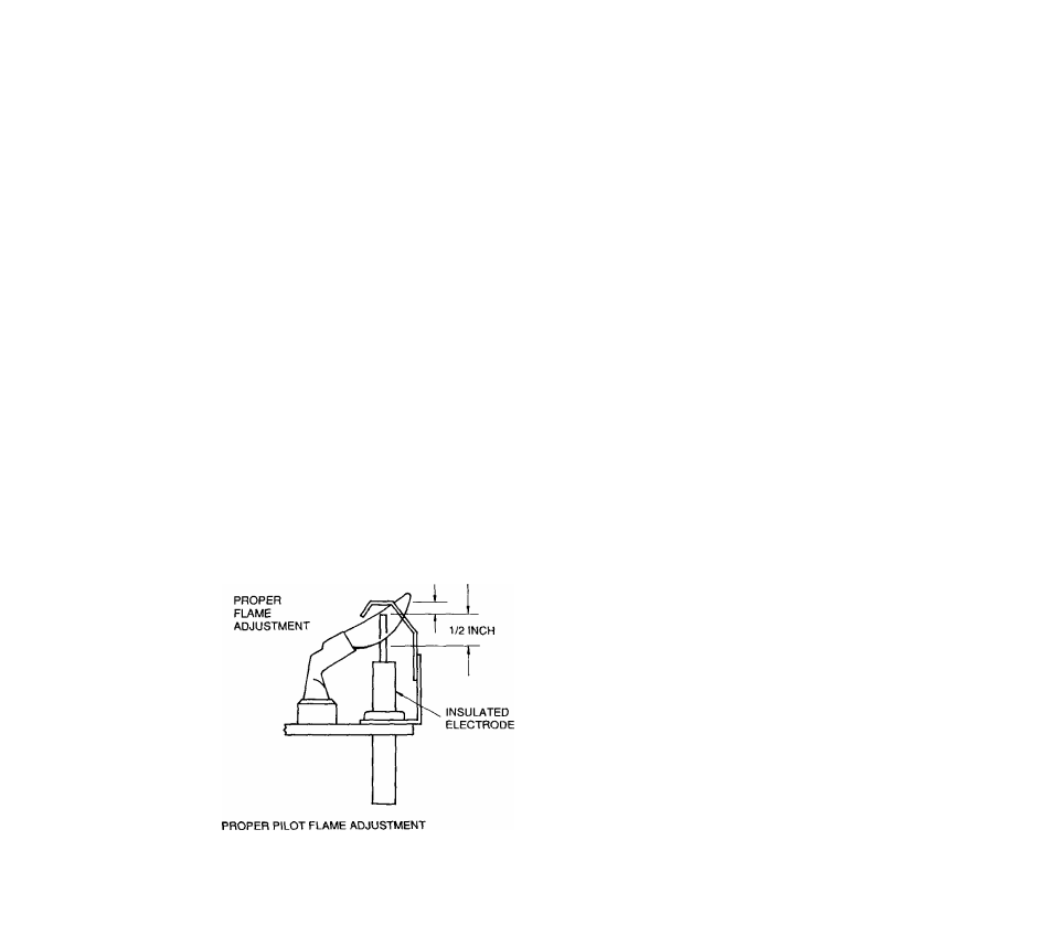
2.
If necessary, adjust spark gap to 3/18" as shown in
Figure 32. Pilot flame should cover 1/2" of tip of
flame sensor.
3/16 INCH
3.
Disconnect pressure switch, red/yeltow, #7/#8 piggy
back wire from pressure switch, terminal ”N.0.”.
4.
Start furnace following Operating Instructions on front
door. Pilot will light; after delay, inducer blower will
come on, but main burners will not light.
5.
Pilot flame should cover 1/2” of tip of flame sensor
as shown in Figure 32.
6.
If you need to adjust pilot flame, remove pilot adjust
ment cover screw on gas control. Save screw for
reinstallation. Turn inner adjustment screw clockwise
-> to decrease pilot flame; counter-clockwise <- to
increase pilot flame. Install cover screw and tighten
to torque of 5 inch-pounds to prevent gas leakage.
7.
Shut off furnace. Connect pressure switch, red/yellow,
#7/#8 piggyback wire to pressure switch, terminal
-N.O.".
8.
If you will not be checking gas input now, turn off
gas. Use manual shut-off valve in gas supply line
just ahead of furnace, Remove shut-off valve from
gas control inlet pressure tap. Install pressure tap
plug. Turn on gas.
9.
Check pilot adjustment cover screw and gas control
inlet pressure tap plug for gas leaks. Use a commer
cial soap solution made for leak detection.
WARNINOi
Never use
an
open flame to check
for gaa leaks. A gas leak could cause
a
firs or
explosion, resulting In damags, Injury or death.
SICTION
20
—
ADJUSTING
MANIFOLD
PRiSSURI.
Equipment Needed: Save time by getting these tools before
you start: Item number(s) 9,10,11,15,19 and 23 listed in Sec
tion 10.
WARNINOi
Correct manifold pressure Is necessary for
proper ignition and burner operation. Use a "U" tube water
manometer to measure actual gaa pressures. Failure to
accurately adjust pressure could cause heat exchanger
failure, asphyxiation, firs or explosion, resulting In dam*
age, Injury or death.
A. Normal manifold pressures (gas control outlet pres
sures).
<3as. Supply
Natural gas
Propane (LP) gas
Normal
3.5 inches W.C.
10.0 inches W.C.
FIGURE 32
CAUTIONi
Many Installers* sat Propane (LP) manifold
pressure at 11.0 Inches W.C. Do not do this. It could
cause heat exchanger failure or nuisance callbacks.
Check gas supply line pressure first, following instruc
tions in Section 19A.
Connect a "U" tube water manometer to measure
manifold pressure:
1.
Turn off gas at manual shut-off valve located in gas
supply line just ahead of furnace.
26