Section 26 — measuring air temperature rise, A, preparing to measure air temperature rise, Measuring air temperature rise – Bard Bayrd Furnace 403293A User Manual
Page 34
Attention! The text in this document has been recognized automatically. To view the original document, you can use the "Original mode".
8.
4.
5.
6
.
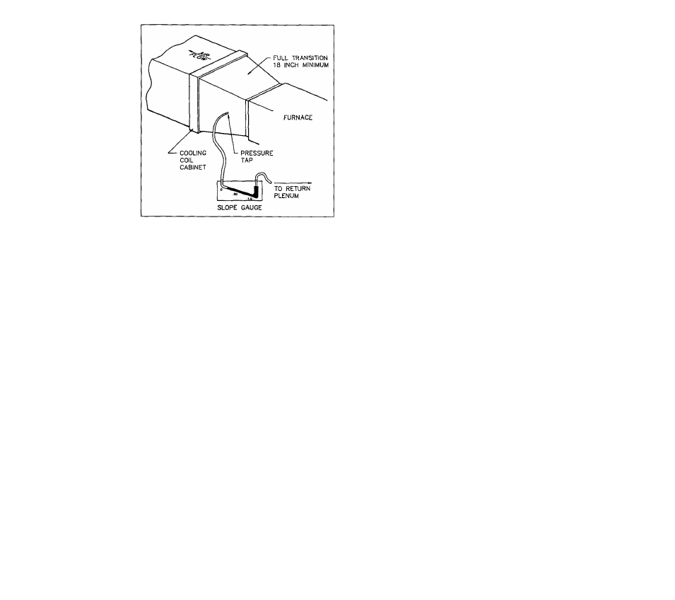
FIGURE 39
Connect pressure tap attached to supply air transi
tion duct (warm air supply plenum) to positive pres
sure side of slope gauge (bottom of scale). See
Figure 39.
Connect pressure tap attached to return air plenum
to negative pressure side of slope gauge (top of
scale). See Figure 39,
Start blower on cooling speed by jumping terminals
"R" and "G" on 24 volt terminal strip located on
furnace control box.
With blower running, read duct work static pressure
from slope gauge.
NOTE: If air filter location is upstream of return air
pressure tap, duct work static pressure must be
adjusted by subtracting 0.08 inches W.C. to get ac
tual duct work static pressure.
Duct Work
Static Pressure
= Measured Pressure -
0.08 inches W.C.
Duct work static pressure should not exceed 0.5
inches W.C. in order to insure proper volume of air
flow.
Remove jumper wire between terminals "R" and "G"
on 24 volt terminal strip. Remove pressure taps and
seal holes in duct work. Failure to seal holes could
result in reduced system performance.
SECTION 26 — MEASURING AIR
TEMPERATURE RISE.
Equipment Needed: Save time by getting these tools before
you start; Item number(s) 21 listed in Section 10.
A, Preparing to measure air temperature rise.
Follow Steps 1 through 5 in Section 25A of this Manual.
B. Measuring air temperature rise.
Air temperature rise (warm air supply temperature mi
nus cold air return temperature) must be within allow
able air temperature rise range specified on furnace
rating plate and in Figure 37B.
Figure 37B shows heating operation speed tap. Fur
nace is set on this speed tap when shipped from fac
tory.
1.
Place thermometer in supply air plenum approxi
mately 2 feet from furnace. Locate thermometer tip
in center of plenum to insure proper temperature
measurement.
2.
Place thermometer in return air duct approximately
2 feet from furnace. Locate thermometer tip in cen
ter of duct to insure proper temperature measure
ment.
3.
Set room thermostat on highest temperature setting.
Operate furnace 6 minutes. Record supply air and
return air temperatures.
4.
Calculate air temperature rise by subtracting return
air temperature from supply air temperature.
5.
a. If air temperature rise is below maximum tem
perature rise, heating system has sufficient air
flow.
b.
If air temperature rise is above maximum tem
perature rise specified in Figure 37B, more
heating air flow ts needed. Change blower
heating speed to a higher setting. Follow in
structions in Section 24 to adjust blower speed.
CAUTIONS
Operating furnace above maxi
mum air temperature rise may cause poor
heating performance and decreased heat
exchanger life.
6.
Heating speed tap should not normally be reduced
below initial factory setting. Some duct system con
figurations and supply register locations may result
in "cold blow". Setting heating speed tap to next
lower speed may resolve this issue.
7.
After making heating airflow adjustments, you must
check air temperature rise following Steps 3 and 4
above to verify that resulting air temperature is within
allowable range.
8.
H air temperature rise is still above that specified
on furnace rating plate and in Figure 37B, check
duct work design with a qualified heating engineer.
It may be necessary to resize the duct work.
Recheck air temperature rise after revising duct
system.
9.
Set room thermostat to desired setting.
10.
Remove thermometers and seal duct work holes.
Failure to seal holes could result in reduced system
performance.
32