Bard Bayrd Furnace 403293A User Manual
Page 26
Attention! The text in this document has been recognized automatically. To view the original document, you can use the "Original mode".
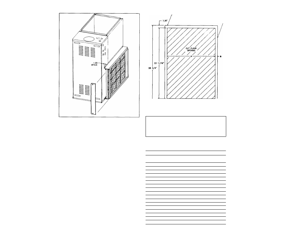
■ВАСЖ OF nLTER CABINET
AND FURNACE CASING
SIDE OF niTER CABINET
AND FURNACE CASING-
UPFLOW SIDE FILTER CABINET
FIGURE 29
1.
Upflow Positions.
a.
Upflow position uses a bottom filter cabinet, side fitter
cabinet or return air filter grille (field supplied).
Manufacturer available bottom and side filter cabi
nets provide correct fitter spacing to assure designed
airflow. Field fabricated filter cabinets should allow
1” spacing between filter and furnace.
b.
1. For upflow side return, use a 16x25 filter,
2.
For upflow air delivery above 1800 CFM use the
following combinations of return air openings;
1.
Bottom only or
2.
1 Side and Bottom or
3.
Both sides.
Use appropriate filter cabinets with combinations
listed above.
c.
See figures 30A and ЗОВ for floor cut out and filter
size of bottom filter cabinet available from manufac
turer.
FILTIR ОШ1МЕТ
A
13-1/16"
15-1/16"
19-1/16"
19-1/16"
в
c
23/32" 14-1/2"
1- 7^52’ 17-.1/2"
23/32" 20-1/2"
2- 7/32" 23-1/2"
UPFLOW FLOOR CUT OUT FOR
BOTTOM FILTER CABINET
FIGURE 30A
Bottom Return Filter Sizes
GAS INPUT
*BTU/HR
MOTOR
*H.P.
FILTER
SIZE
40,000
1/4
14
X
25
40,000
1/3
14x 25
60.000
1/4
14x 25
60,000
1/3
14x 25
60,000
1/2
16
X
25
80,000
1/4
14x 25
80,000
1/3
14x 25
80,000
1/2
1 6 x 2 5
80,000
3/4
20
X
25
100,000
1/3
16x 25
100,000
1/2
16
X
25
100,000
3/4
20x 25
120,000
1/2
20x 25
120,000
3/4
20x 25
140,000
3/4
20
X
25
140.000
3/4
20
X
25
‘See furnace rating plate located on blower door.
FIGURE ЗОВ
24