Bard Bayrd Furnace 403293A User Manual
Page 8
Attention! The text in this document has been recognized automatically. To view the original document, you can use the "Original mode".
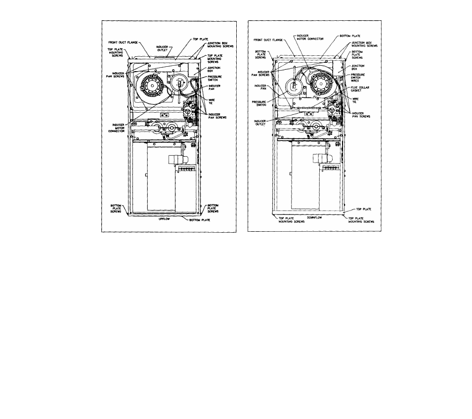
AS-SHIPPED CONFIGURATION
FIGURE 4
2.
Remove two junction box mounting screws from top
plate. Remove four top plate mounting screws. Save
all screws. Remove top plate and front duct flange.
3.
Disconnect pressure switch wires and inducer motor
connector wires.
4.
Remove ten screws from the inducer pan; save
screws. DO NOT drop screws into heat exchanger
openings.
5.
Lift inducer pan (with inducer motor and pressure
switch stilt in place) about 1/4 inch and tilt left side
up to clear casing flanges. Use care not to damage
inducer gasket.
NOTE: If possible, decide on direction of gas entry
now. Screws to inlet gas valve fitting are accessible.
See Section 11.
6.
Rotate inducer pan 180 degrees, line up mounting
holes and place inducer pan in furnace. Use care
not to damage gasket. Replace ten screws in in
ducer pan. See Figure 5.
CONVERTED CONFIGURATION
FIGURE 5
7.
Pressure switch wires will no longer reach pressure
switch. Remove cable tie around excess length of
red/yellow piggyback, blue and purple pressure switch
wires.
8.
Connect pressure switch wires as follows. Wires are
numbered on insulation near terminals.
a. #1 Purple wire to pressure switch, terminal 'C
(Common).
b.
#2 Blue wire to pressure switch, terminal 'NC
(Normally Closed).
c.
#7 and #8 Red/Yellow piggyback wire to pres
sure switch, terminal 'NO' (Normally Open).
d.
Route all pressure switch wires over inducer
motor.
e.
Reconnect inducer motor connector.
f.
Replace wire tie in area that prevents wires from
touching hot surfaces.